Safe valve group for pump

A technology for safety valves and pumps, applied in the field of hydraulic components, can solve the problems of high bypass pressure of safety valves, inconvenient disassembly and maintenance, unstable system pressure, etc., achieving small compression capacity, convenient assembly, disassembly and maintenance, Reduce the effect of connecting pipes

Inactive Publication Date: 2010-11-24
SHANGHAI LIXIN HYDRAULIC
View PDF0 Cites 0 Cited by
  • Summary
  • Abstract
  • Description
  • Claims
  • Application Information

AI Technical Summary

Problems solved by technology

[0003] There are many connecting pipes between the existing safety valve and the pump and the system, which makes its disassembly and maintenance very inconvenient, and it is easy to cause leakage
In addition, the bypass pressure of the existing safety valve is high, making the system pressure unstable

Method used


Image

  • Safe valve group for pump
  • Safe valve group for pump
  • Safe valve group for pump

Examples


Embodiment 1

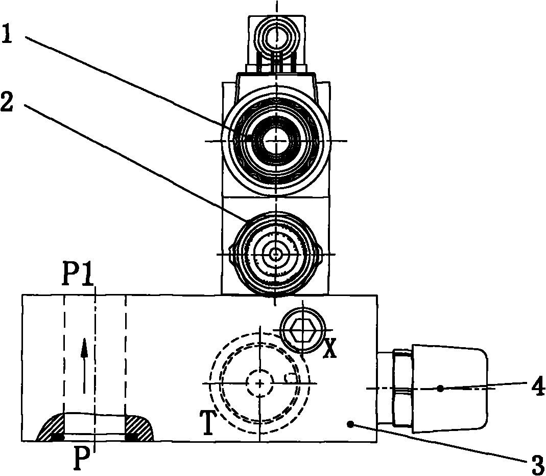
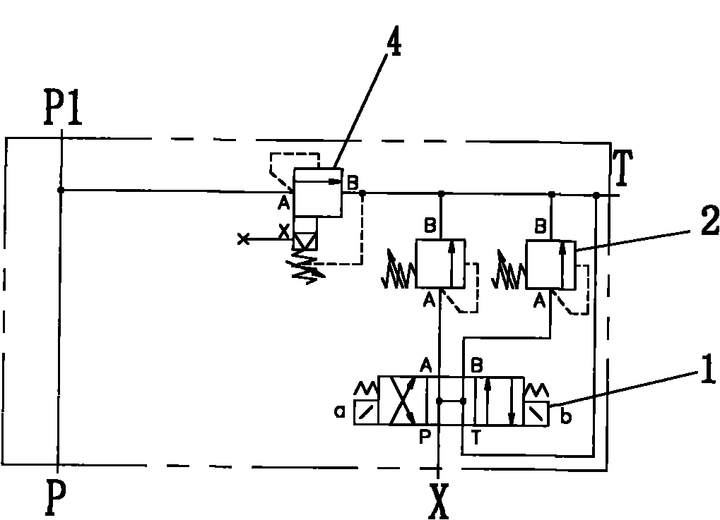
[0020] see figure 1 , 2 , and 3, the pump safety valve group, including a valve body 3, an electromagnetic reversing valve 1, a superposition relief valve 2 and a cartridge relief valve 4.

[0021] An oil inlet P, an oil outlet P1, an oil return port T and a control port X are processed on the valve body 3 to communicate with the main oil circuit. The upper surface of the valve body 3 is also provided with a through hole for connecting the main oil circuit of the valve body and the control oil circuit of the superposition relief valve 2 . A mounting hole is machined on the left end of the valve body for mounting a cartridge relief valve 4 .

[0022] The superimposed relief valve 2 is installed on the upper surface of the valve body 3 through bolts, and the superimposed relief valve communicates with the oil inlet P, the oil outlet P1, the oil return port T and the control port X of the valve body. The electromagnetic reversing valve 1 is fixedly mounted on the superimposed ...

Embodiment 2

[0033] Such as Figure 4 The shown pump safety valve group includes a valve body 3 , an electromagnetic reversing valve 1 , a stacked relief valve 2 and a cartridge relief valve 4 .

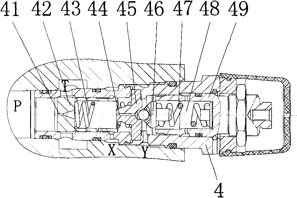
[0034] Oil inlet P, oil outlet P1, oil return port T, control port X, throttling port 6 and pressure measuring port M are processed on the valve body 3 to communicate with the main oil circuit. A damper 7 is arranged in the control channel of the valve body 3 . The upper surface of the valve body 3 is also provided with a through hole for connecting the main oil circuit of the valve body and the control oil circuit of the superposition relief valve 2 . A mounting hole is machined on the left end of the valve body for mounting a cartridge overflow valve 4 .

[0035] The superimposed overflow valve 2 is installed on the upper surface of the valve body 3 through bolts, and the electromagnetic reversing valve 1 is fixed on the superimposed overflow valve 2 through bolts. The left end surface of th...


PUM


Abstract

The invention relates to a safe valve group for a pump, comprising a valve body, a plug-in overflowing valve, a stacked overflowing valve and an electromagnetic reversing valve. The valve body is internally provided with an oil inlet (P), an oil outlet (P1), an oil return opening (T) and a control opening (X) communicated with a main oil way, the plug-in overflowing valve and the stacked overflowing valve are mounted on the valve body and communicated with the oil inlet (P), the oil outlet (P1), the oil return opening (T) and the control opening (X), and the electromagnetic reversing valve is fixedly mounted on the stacked overflowing valve. The invention has the advantages of reduced connection pipeline number, lessened leakage, low bypass pressure because of short path, approximate zero starting and bypass pressure of the pump, stabilized system pressure, improved performance and reduced noise because of small compression column and smooth switching to low-pressure bypass and can be directly mounted on an SAE (Society of Automotive Engineers) pressure oil port of the pump so as to reduce space and be convenient mount, dismount and maintain.

Description

technical field [0001] The invention relates to a hydraulic component, in particular to a pump safety valve group used to relieve system pressure. Background technique [0002] Usually, heavy-duty construction equipment drives the actuator to work by discharging the hydraulic fluid from the hydraulic pump. The hydraulic fluid discharged from the hydraulic pump is supplied to different actuators through a control valve that controls the flow of the fluid. The safety valve is installed In the control valve, when the pressure in the hydraulic circulation line exceeds the set working pressure, the working fluid is discharged into the pressure oil tank to keep the system stable. [0003] There are many connecting pipes between the existing safety valve and the pump and the system, which makes its disassembly and maintenance very inconvenient and easily causes leakage. In addition, the bypass pressure of the existing safety valve is high, making the system pressure unstable. Co...

Claims


Application Information

Patent Timeline
Patent Type & Authority Applications(China)
IPC IPC(8): F15B13/02
Inventor 袁才富刘峰伟金丹朱剑根沈至伟
Owner SHANGHAI LIXIN HYDRAULIC
Why Eureka
Try Eureka