Frequency variable compressor and control method thereof

a compressor and variable speed technology, applied in the direction of machines/engines, liquid fuel engines, lighting and heating apparatus, etc., can solve the problem that the variable speed dc inverter compressor has the longest yearly operating time in the low to mid speed range, and achieves the effect of reducing over-compression loss, small compression capacity and high efficiency

Inactive Publication Date: 2011-11-10
LG ELECTRONICS INC
View PDF5 Cites 22 Cited by
  • Summary
  • Abstract
  • Description
  • Claims
  • Application Information

AI Technical Summary

Benefits of technology

[0065]In the frequency variable compressor and the control method thereof according to the present invention, although a small compression capacity is required, the compressor can be operated in the mid to high speed operation range in which the frequency variable motor has relatively high efficiency, unlike the conventional twin compressor.
[0066]Additionally, in the frequency variable compressor and the control method thereof according to the present invention, the compressor compresses the refrigerant by the 2-stage compression method at a low operating frequency in which efficiency of the frequency variable motor is degraded, and thus reduces an over-compression loss more than by a one-stage compression method or a twin compression method. There is an advantage of improving efficiency of the compressor during the low-capacity compression operation of relatively high using frequency.
[0067]Moreover, in the frequency variable compressor and the control method thereof according to the present invention, when a cooling capacity required for compression increases, the compressor converts the compression method into the twin compression method and raises the operating frequency of the frequency variable motor to increase the compression capacity. Accordingly, it is possible to increase the compressible capacity range of the compressor and considerably improve energy efficiency of the compressor.

Problems solved by technology

However, the variable speed DC inverter compressor has the longest yearly operating time in the low to mid speed range.

Method used


Image

  • Frequency variable compressor and control method thereof
  • Frequency variable compressor and control method thereof
  • Frequency variable compressor and control method thereof

Examples


first embodiment

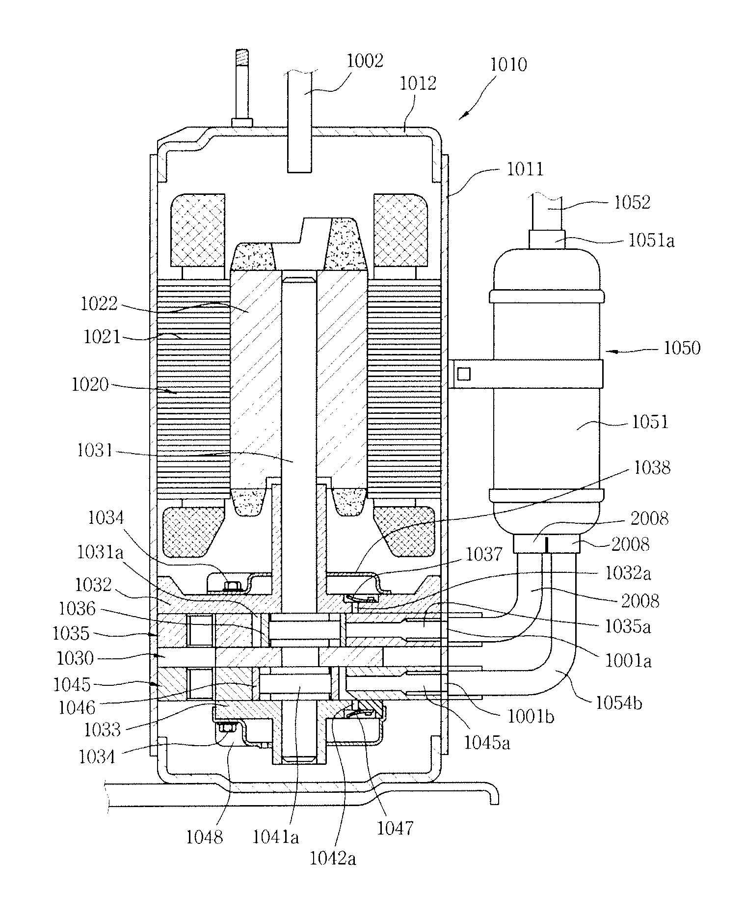
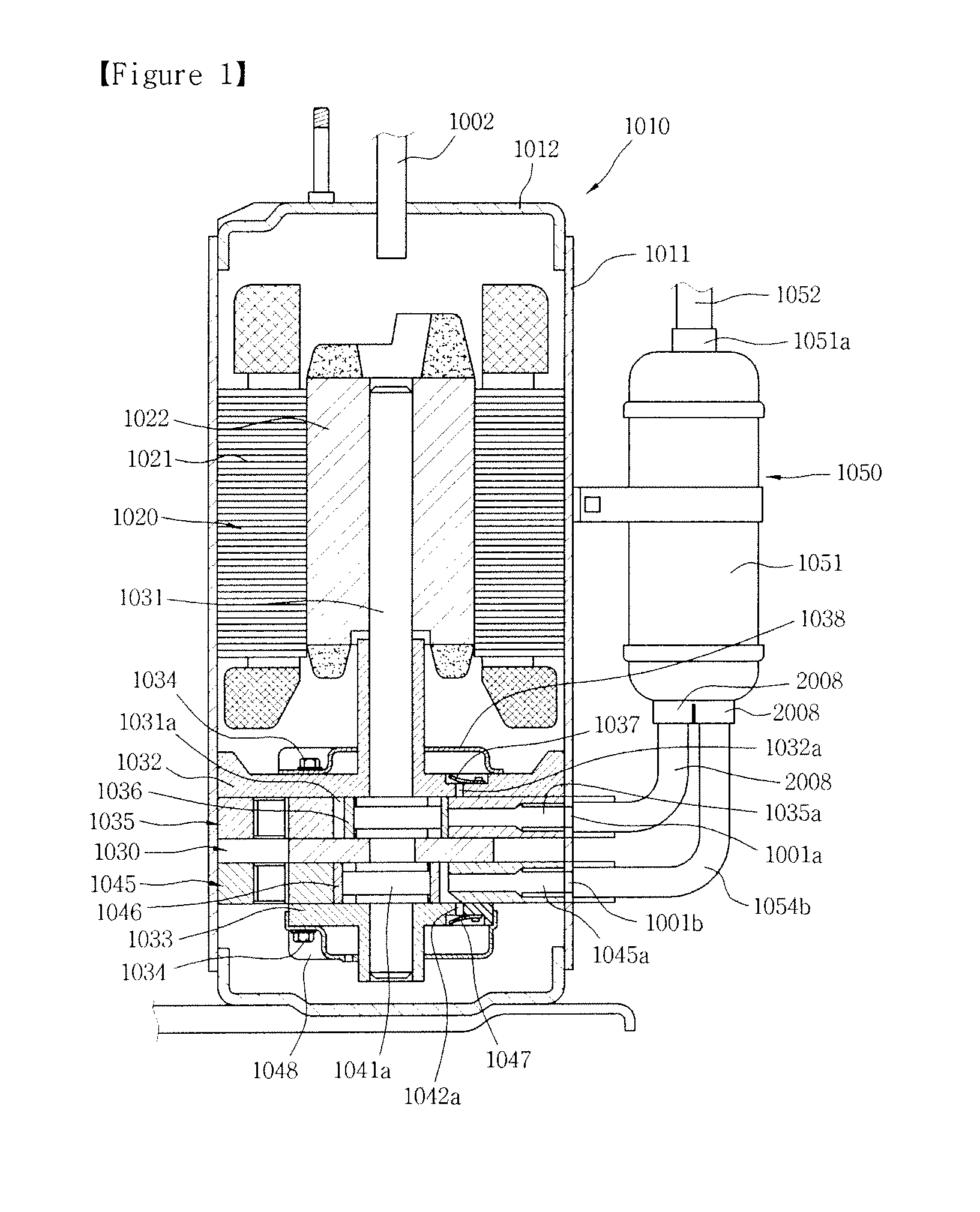
[0092]The frequency variable compressor includes a shell 100 forming the external appearance of the compressor, a DC variable speed frequency variable motor 200 (hereinafter, referred to as ‘frequency variable motor’) is installed in the shell 100 as a motor unit, and a rotating shaft 300 transferring a rotational force of the frequency variable motor 200 is connected to the frequency variable motor 200. According to the present invention, the frequency variable motor 200 is positioned on the upper side in the shell 100, and the rotating shaft 300 is downwardly extended from the frequency variable motor 200. A compression mechanism unit 400 is installed below the frequency variable motor 200, receives power from the frequency variable motor 200 through the rotating shaft 300, and compresses the refrigerant. The compression mechanism unit 400 includes a first compression mechanism unit 410 and a second compression mechanism unit 420 which are rotary compression mechanisms. That is, t...

second embodiment

[0102]According to the present invention, a mid-pressure passage 830′ penetrates an upper portion of the shell 100. This can significantly reduce piping vibration generated in the mid-pressure passage 830′. Moreover, in the drawings, a discharge passage 820 and a first discharge port 610 are formed in the opposite direction to a mid-pressure discharge valve 510 and a second discharge port 620 such that the discharge passage 820 and the first discharge port 610 do not overlap with the mid-pressure discharge valve 510 and the second discharge port 620. However, actually, the discharge passage 820 and the first discharge port 610 are very close to the mid-pressure discharge valve 510 and the second discharge port 620. If the discharge passage 820 is distant from the mid-pressure discharge valve 510, i.e., if the discharge passage 820 is distant from a discharge hole 410d of a first compression mechanism unit 410, when the refrigerant flows, its pressure loss is generated in the lower b...

third embodiment

[0105]FIGS. 10 and 11 are views of a frequency variable compressor according to the present invention. FIG. 10 illustrates a state where the compressor compresses refrigerant by a twin compression method, and FIG. 11 illustrates a state where the compressor compresses refrigerant by a 2-stage compression method.

[0106]Like the first and second embodiments, the frequency variable compressor according to the third embodiment of the present invention includes a shell 100, a frequency variable motor 200, a rotating shaft 300, a compression mechanism unit 400, a lower bearing 500, an upper bearing 600, a valve 700 and an accumulator 900. The third embodiment is the same as the first and second embodiments except the construction of suction passages and discharge passages.

[0107]First, the driving by the twin compression method will be described with reference to FIG. 10. The refrigerant is sucked into a first compression mechanism unit 410 through a first suction passage 810, compressed th...


PUM


Abstract

The present invention discloses a frequency variable compressor, including a shell defining an airtight space, an accumulator temporarily storing refrigerant before introducing the refrigerant into the shell, a first compression mechanism unit positioned in the shell, including a rolling piston, a cylinder, a refrigerant suction hole, a refrigerant discharge hole and a vane, and compressing refrigerant, a second compression mechanism unit positioned in the shell, including a rolling piston, a cylinder, a refrigerant suction hole, a refrigerant discharge hole and a vane, and compressing refrigerant, a frequency variable motor positioned in the shell and transferring power to the rolling pistons of the first and second compression mechanism units through a rotating shaft, and a valve controlling the flow of the refrigerant such that the first and second compression mechanism units compress the refrigerant by a twin rotary compressor type or a 2-stage rotary compressor type.

Description

TECHNICAL FIELD[0001]The present invention relates to a frequency variable compressor.BACKGROUND ART[0002]In general, a compressor is a mechanical apparatus receiving power from a power generation apparatus such as an electric motor, a turbine or the like, and compressing the air, refrigerant or various operating gases to raise a pressure. The compressor has been widely used for electric home appliances such as refrigerators and air conditioners, and the application thereof has been expanded to the whole industry.[0003]The compressors are roughly classified into a reciprocating compressor in which a compression space into / from which an operating gas is sucked and discharged is defined between a piston and a cylinder and the piston is linearly reciprocated in the cylinder to compress refrigerant, a rotary compressor in which a compression space into / from which an operating gas is sucked and discharged is defined between an eccentrically-rotated roller and a cylinder and the roller is...

Claims


Application Information

Patent Timeline
Patent Type & Authority Applications(United States)
IPC IPC(8): F25B49/00
CPCF04C18/356F04C23/001F04C23/008F04C2240/804F04C28/065F04C28/08F04C28/24F04C28/02F04C18/00F04C29/00
Inventor LEE, SEUNG-JUN
Owner LG ELECTRONICS INC
Why Eureka
Try Eureka