Bearing

A technology of bearings and shaft holes, applied in the field of bearings, can solve the problems of cloth deviation and wrinkling of cloth guide rollers, increase production costs, and fast wear of the edges of shaft holes, etc., and achieve the effect of reducing production costs and prolonging service life

Inactive Publication Date: 2013-03-13
张家港市广达密封有限公司
View PDF6 Cites 0 Cited by
  • Summary
  • Abstract
  • Description
  • Claims
  • Application Information

AI Technical Summary

Problems solved by technology

Because the cloth guide roller is very long, plus the friction with the shaft sleeve during the rotation process, and a large amount of solid matter enters the gap between the shaft head and the shaft sleeve, the edge of the shaft hole wears quickly, and the cloth guide roller The shaft head is also subject to different degrees of wear. When the shaft heads at both ends of the cloth guide roller are worn to different degrees, the cloth guide roller will tilt, which will cause the cloth on the cloth guide roller to deviate and wrinkle, so it needs to be replaced frequently Shaft sleeve or the whole cloth guide roller, because the cloth guide roller is expensive, which increases the production cost

Method used


Image

  • Bearing
  • Bearing
  • Bearing

Examples


Embodiment Construction

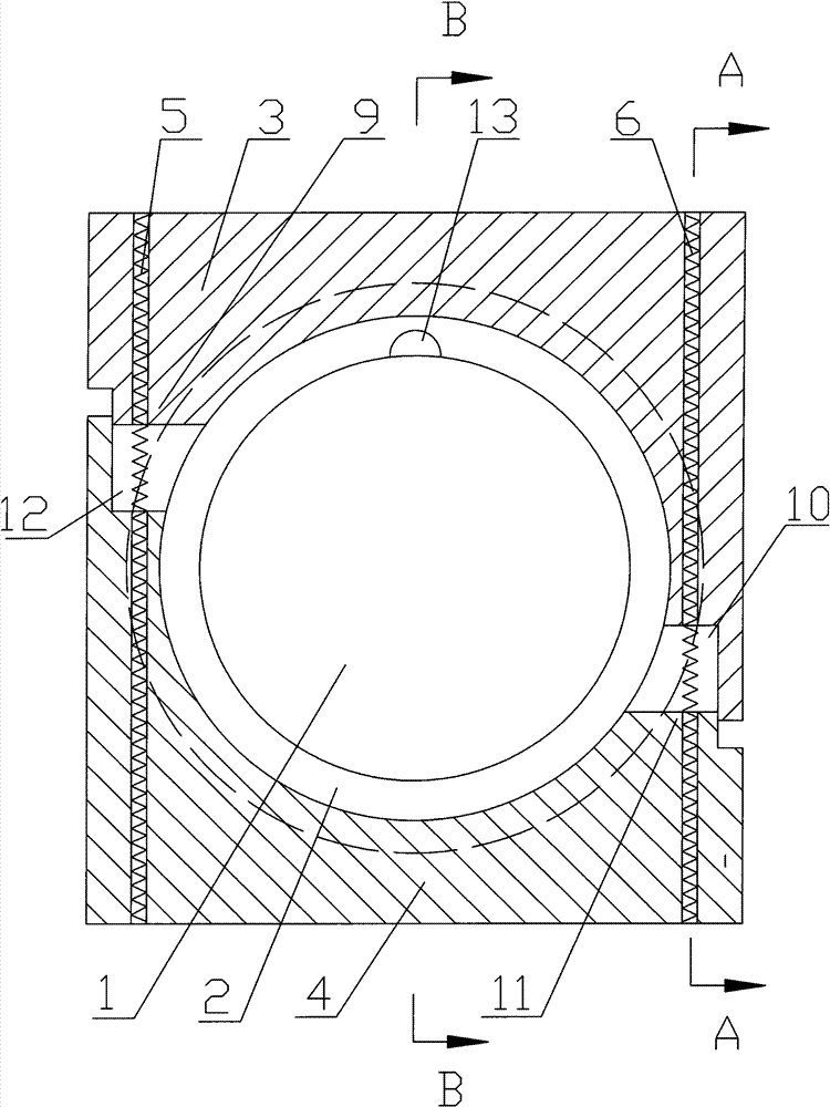
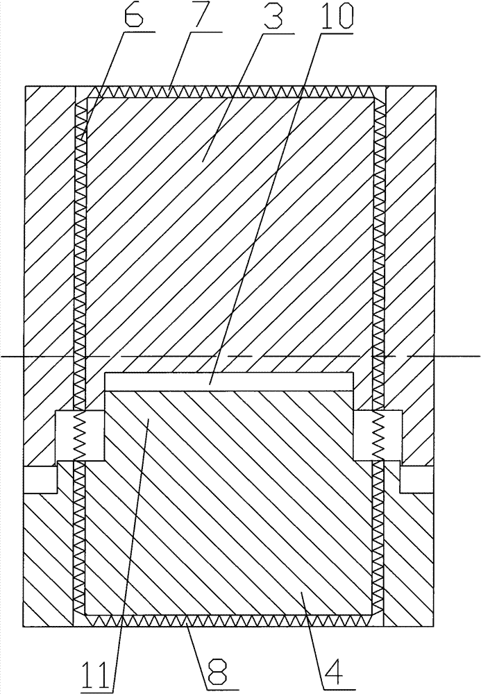
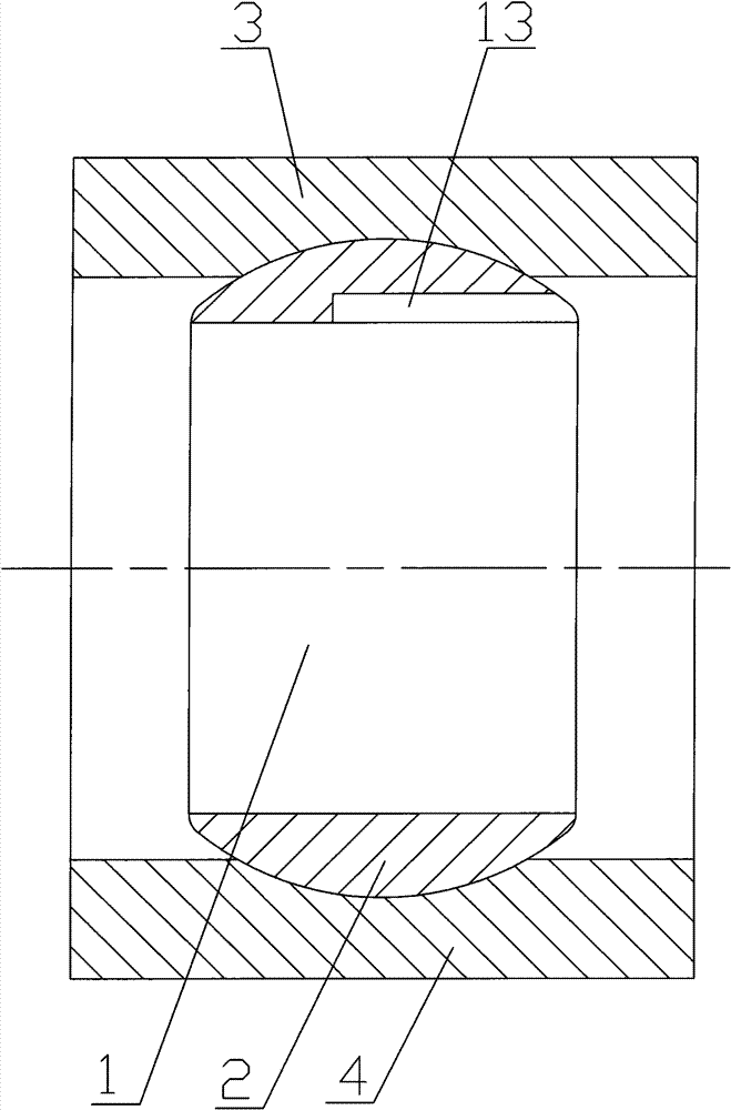
[0013] The technical solution of the present invention, its working principle and advantages will be further described below in conjunction with the accompanying drawings and specific embodiments.

[0014] Such as figure 1 , figure 2 and image 3 As shown, a bearing includes a ball sleeve 2 with a shaft hole 1. The outer surface of the ball sleeve 2 is spherical, and a shaft sleeve is arranged outside the ball sleeve 2. The shaft sleeve is composed of an upper half shaft sleeve 3 and a lower half shaft sleeve. 4 composition, in this embodiment, in order to install the bearing conveniently, the outer surfaces of the upper half bushing 3 and the lower half bushing 4 are respectively provided with an upper tension spring groove 7 and a lower spring groove 8, and the upper half bushing 3 and the lower half bushing The lower half shaft sleeve 4 is closed together by the left extension spring 5 and the right extension spring 6, and the extension springs located outside the upper ...


PUM


Abstract

The invention discloses a bearing which avoids the abrasion of a guide roller and prolongs the service life of the guide roller. The bearing comprises a ball sleeve having axle holes, wherein the external surface of the ball sleeve is spherical; a shaft sleeve is arranged outside the ball sleeve and is formed by folding two half shaft sleeves together through a tension spring; and the spherical external surface of the ball sleeve is in clearance fit with the spherical internal surface of the shaft sleeve. The bearing is suitable for places where the guide roller is arranged in the printing and dyeing industry.

Description

technical field [0001] The invention relates to a bearing, in particular to a bearing used on a cloth guide roller in printing and dyeing equipment. Background technique [0002] At present, in printing and dyeing, the bearings are: square shaft sleeves, which are usually fixedly installed on the box wall or support frame in the printing and dyeing equipment, and there are shaft holes inside the shaft sleeves. The shaft hole of the shaft sleeve is enough. Because the cloth guide roller is very long, plus the friction with the shaft sleeve during the rotation process, and a large amount of solid matter enters the gap between the shaft head and the shaft sleeve, the edge of the shaft hole wears quickly, and the cloth guide roller The shaft head is also subject to different degrees of wear. When the shaft heads at both ends of the cloth guide roller are worn to different degrees, the cloth guide roller will tilt, which will cause the cloth on the cloth guide roller to deviate ...

Claims


Application Information

Patent Timeline
Patent Type & Authority Patents(China)
IPC IPC(8): F16C35/063F16C23/08
Inventor 孙平
Owner 张家港市广达密封有限公司
Why Eureka
Try Eureka