Installation structure of cloth guide roller in dyeing device

The technology of printing and dyeing equipment and installation structure is applied in the field of installation structure of cloth guide rollers, which can solve the problems of increasing production cost, deviation and wrinkling of cloth guide rollers, expensive cloth guide rollers, etc., so as to prolong the service life and reduce production. cost effect

Inactive Publication Date: 2010-03-31
张家港市广达密封有限公司
View PDF0 Cites 0 Cited by
  • Summary
  • Abstract
  • Description
  • Claims
  • Application Information

AI Technical Summary

Problems solved by technology

Because the cloth guide roller is very long, plus the friction with the shaft sleeve during the rotation process, and a large amount of solid matter enters the gap between the shaft head and the shaft sleeve, the edge of the shaft hole wears quickly, and the cloth guide roller The shaft head is also subject to different degrees of wear. When the shaft heads at both ends of the cloth guide roller are worn to different degrees, the cloth guide roller will tilt, which will cause the cloth on the cloth guide roller to deviate and wrinkle, so it needs to be replaced frequently Shaft sleeve or the whole cloth guide roller, because the cloth guide roller is expensive, which increases the production cost

Method used


Image

  • Installation structure of cloth guide roller in dyeing device
  • Installation structure of cloth guide roller in dyeing device

Examples


Embodiment Construction

[0014] The technical solution of the present invention, its working principle and advantages will be further described below in conjunction with the accompanying drawings and specific embodiments.

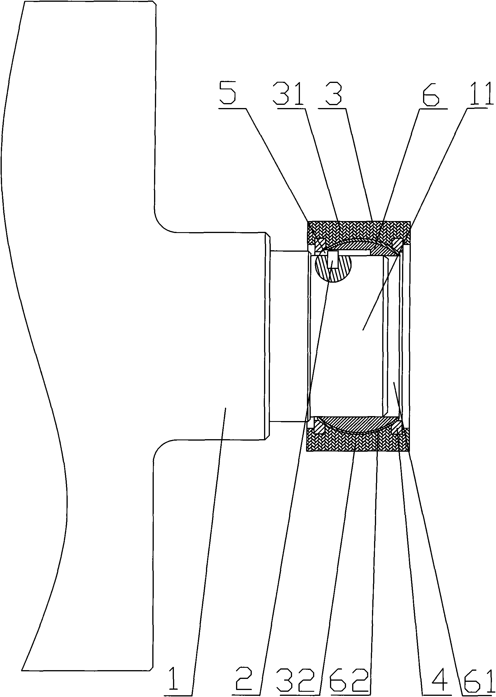
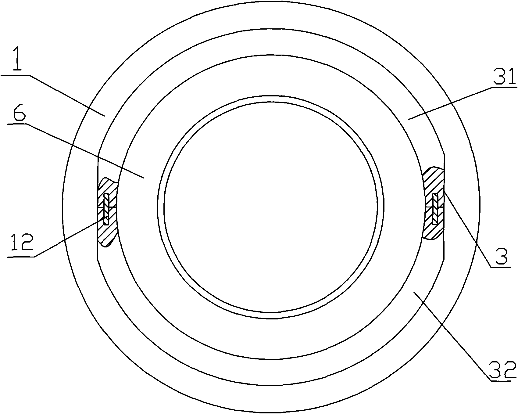
[0015] figure 1 , figure 2 As shown, the installation structure of the cloth guide roller in a kind of printing and dyeing equipment, the shaft head 11 of the cloth guide roller 1 is arranged in the shaft hole 61 of the ball sleeve 6 made of stainless steel and connected with the ball sleeve 6, the ball sleeve 6 The outer surface of the ball is spherical, and the outer surface of the ball sleeve 6 is provided with a wear-resistant layer 62, which prolongs the service life of the ball sleeve 6. A shaft sleeve 3 is arranged on the outside of the ball sleeve 6, and the shaft sleeve 3 is made of ultra-high polymer material or graphite. In this embodiment, the shaft sleeve 3 is composed of two half shaft sleeves 31, 32 closed by the pin shaft 12 , In actual production, tie hoops can ...


PUM


Abstract

The invention discloses an installation structure of a cloth guide roller in a dyeing device, comprising the cloth guide roller, a shaft head of the cloth guide roller is arranged in a shaft hole of aball sleeve and connected with the ball sleeve, the outer surface of the ball sleeve is spherical, a shaft sleeve is arranged outside the ball sleeve and formed by closing two half shaft sleeves, andthe spherical outer surface of the ball sleeve is in clearance matching with the spherical inner surface of the shaft sleeve. The invention is suitable for places for installing cloth guide rolls inthe dyeing industry.

Description

technical field [0001] The invention relates to the installation structure of cloth guide rollers in printing and dyeing equipment. Background technique [0002] At present, in terms of printing and dyeing, the installation structure of the cloth guide roller in the printing and dyeing equipment is: square bushing, the square bushing is usually fixedly installed on the box wall or support frame in the printing and dyeing equipment, and there is a shaft hole inside the bushing. The shaft head of the cloth guide roller can be put into the shaft hole of the shaft sleeve. Because the cloth guide roller is very long, plus the friction with the shaft sleeve during the rotation process, and a large amount of solid matter enters the gap between the shaft head and the shaft sleeve, the edge of the shaft hole wears quickly, and the cloth guide roller The shaft head is also subject to different degrees of wear. When the shaft heads at both ends of the cloth guide roller are worn to di...

Claims


Application Information

Patent Timeline
Patent Type & Authority Applications(China)
IPC IPC(8): D06B23/04
Inventor 孙平
Owner 张家港市广达密封有限公司
Why Eureka
Try Eureka