Hydraulic support

A technology of hydraulic supports and supporting beams, which is applied in pillars/supports, mining equipment, earthwork drilling and mining, etc. It can solve problems such as the jamming of telescopic beams, the inability of telescopic beams to move, and the inability of jacks to keep in sync, etc., to reduce the beam end Distance, the effect of solving the phenomenon of chip gang and caving phenomenon

Active Publication Date: 2010-12-01
益阳市科技成果转化服务中心 +1
View PDF7 Cites 5 Cited by
  • Summary
  • Abstract
  • Description
  • Claims
  • Application Information

AI Technical Summary

Problems solved by technology

In the hydraulic support of this structure, there is sliding friction between the telescopic beam device and the supporting beam, and the friction force between the two is relatively large, so that the two jacks often cannot keep in sync during the working process, so the telescopic beam is in the process of stretching. There will be an offset in the middle, and then the leftmost side wall or the rightmost side wall of the telescopic beam will produce greater friction on the supporting beam. When the friction force is greater than the force of the jack on the telescopic beam, the telescopic beam will The jamming phenomenon occurs, which makes the telescopic beam unable to perform the telescopic movement smoothly

Method used


Image

  • Hydraulic support
  • Hydraulic support
  • Hydraulic support

Examples


Embodiment Construction

[0031] The core of the present invention is to provide a hydraulic support, the friction between the telescopic beam and the support beam of the hydraulic support is small, and the telescopic beam will not be stuck.

[0032] In order to enable those skilled in the art to better understand the technical solutions of the present invention, the present invention will be further described in detail below in conjunction with the accompanying drawings and specific embodiments.

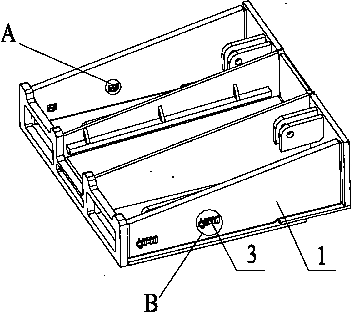
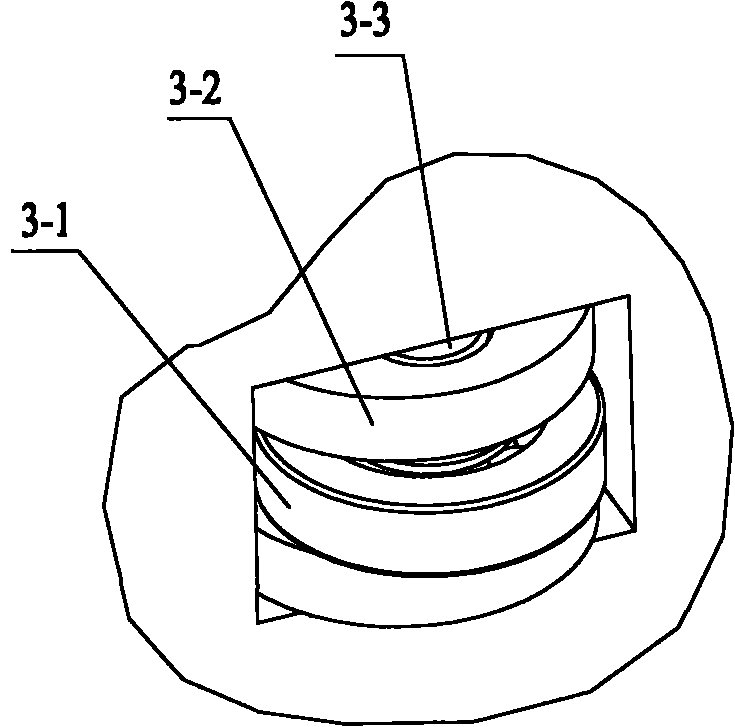
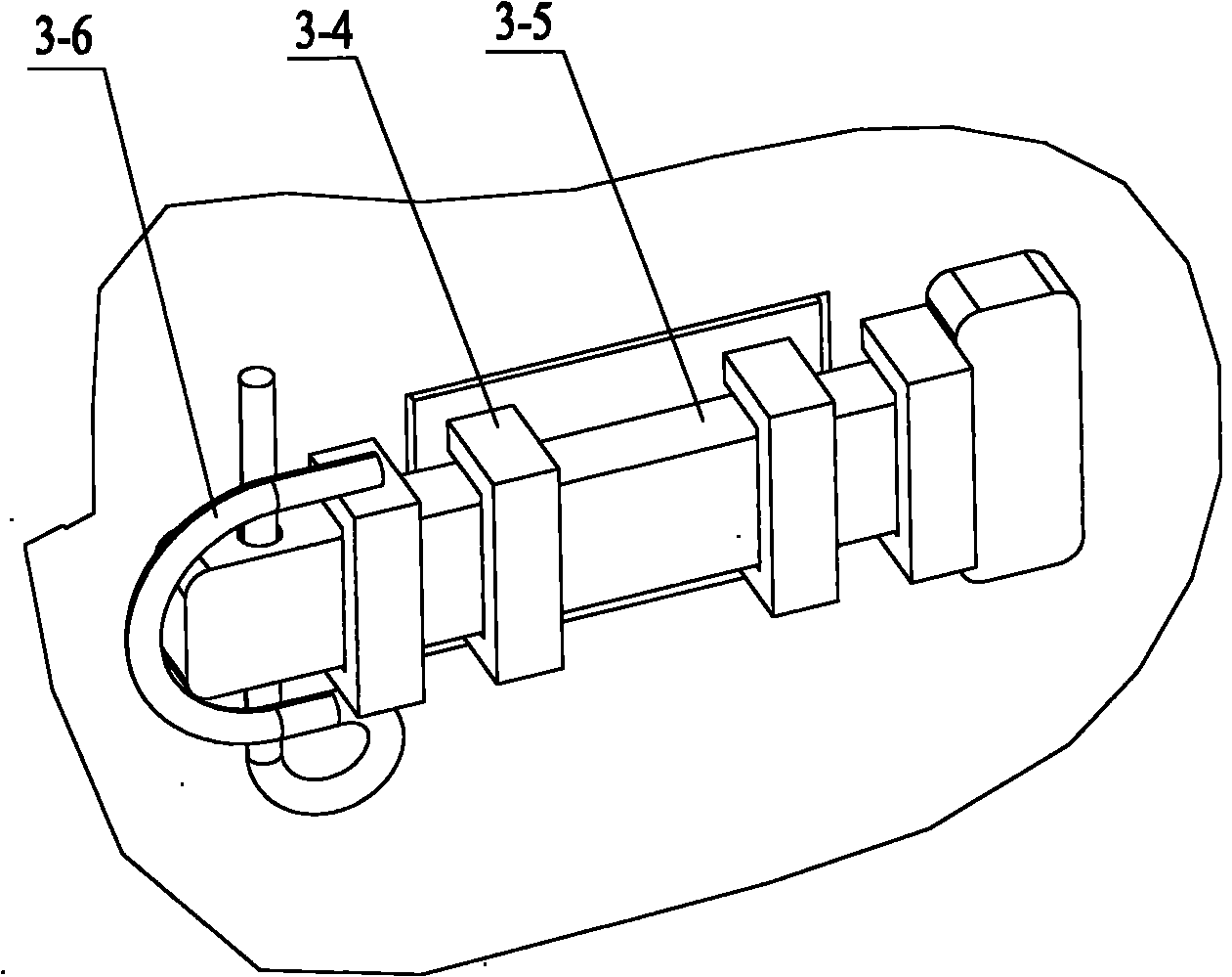
[0033] Please see Figure 1-Figure 3 , figure 1 It is a structural schematic diagram of a specific embodiment of the hydraulic support provided by the present invention; figure 2 for figure 1 The schematic diagram of the enlarged structure at A; image 3 for figure 1 Schematic diagram of the enlarged structure at B.

[0034] The hydraulic support provided by the present invention includes a telescopic beam and a support beam, wherein the support beam can be a top beam or a hinged front beam, and the fo...


PUM


Abstract

The invention relates to the technical field of coal-cutting machinery, and discloses a hydraulic support, which comprises a supporting beam and a flexible beam, wherein at least one guiding device is arranged between the lateral surface of the flexible beam and the supporting beam; rolling friction is formed between the flexible beam and the supporting beam due to the guiding device; under the action of the guiding device, the flexible beam is unlikely to offset under the driving of a driving device; the rolling friction is formed between the flexible beam and the supporting beam, so the frictional force between the flexible beam and the supporting beam is far smaller than the acting force applied by the driving device on the flexible beam; and thus, the flexible beam avoids being lockedand blocked and can make flexible motion normally all the time; and when a top plate of a working surface is broken, the flexible beam can extend out in time to reduce the end-to-end distance of the beam, and the problems of wall caving and falling which are generated in the operating process of the hydraulic support are solved consequently.

Description

technical field [0001] The invention relates to the technical field of coal mining machinery, in particular to a hydraulic support. Background technique [0002] The hydraulic support is an important part of coal mine comprehensive mechanized mining equipment. The hydraulic support can reliably and effectively support and control the roof of the working face, isolate the goaf, prevent gangue from entering the mining face, and maximize the safety of coal miners. [0003] During the working process of comprehensive mechanized mining equipment in coal mines, there must be a distance between the front end of the support beam (such as the top beam or hinged front beam) of the hydraulic support and the coal wall line, which is called the beam end distance. The coal wall may have slab phenomenon (the so-called slab phenomenon refers to the phenomenon that the coal wall is deformed, damaged or even fallen off under the action of mine pressure), and the roof within the range of the b...

Claims


Application Information

Patent Timeline
Patent Type & Authority Applications(China)
IPC IPC(8): E21D15/16E21D15/51
Inventor 柯昌青王宇刘德利李怀志
Owner 益阳市科技成果转化服务中心
Why Eureka
Try Eureka