

Cleaning device and cleaning performance maintaining method
A cleaning device and cleaning technology, which is applied in the fields of instruments, optics, electrical recording, etc., can solve the problem of not being able to fully suppress the adhesion
- Summary
- Abstract
- Description
- Claims
- Application Information
AI Technical Summary
Problems solved by technology
Method used
Image

Examples
no. 1 approach
[0028] First, the first embodiment will be described.
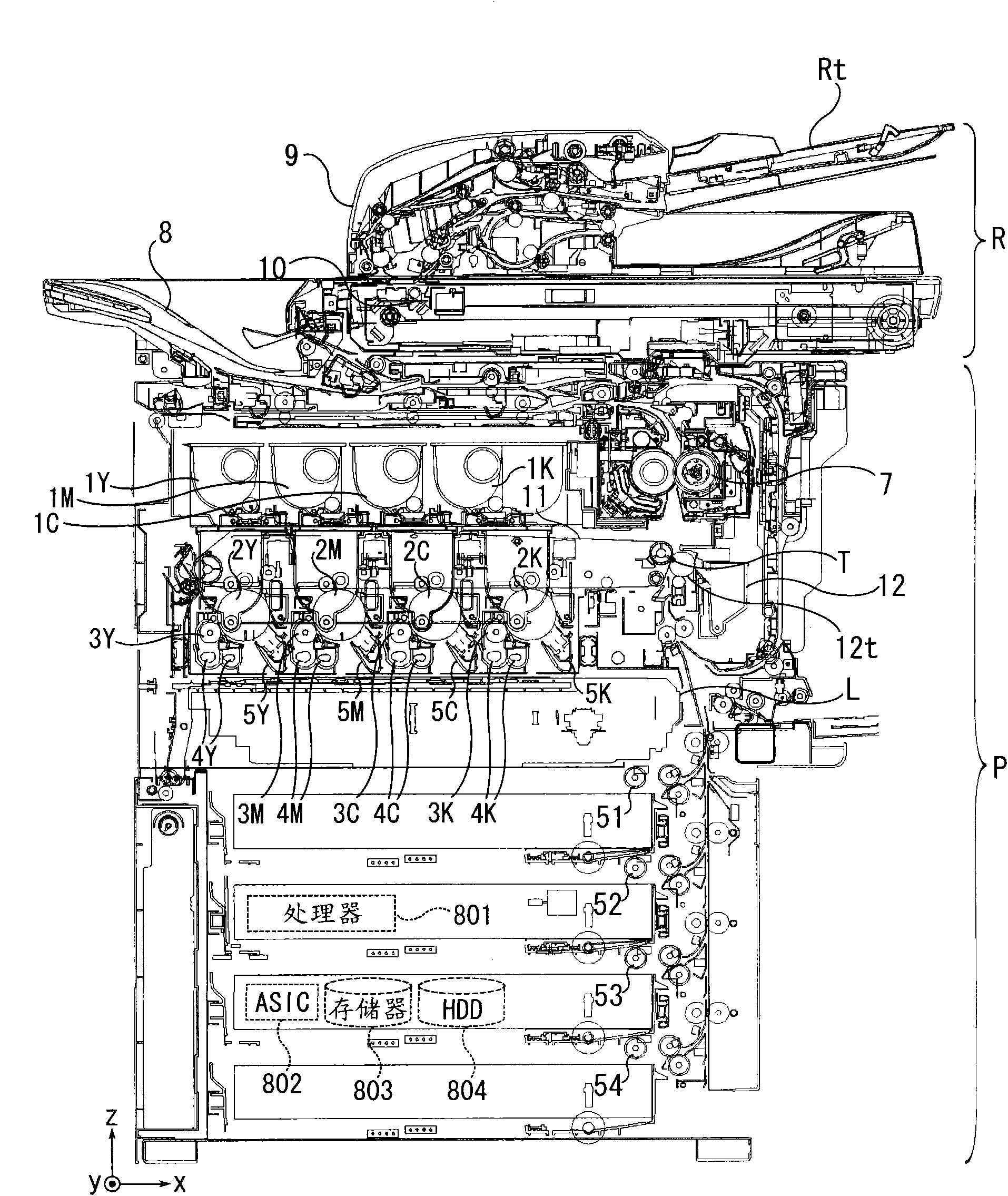
[0029] figure 1 is a longitudinal sectional view of the image forming apparatus.
[0030] The image forming apparatus includes an image reading unit R and an image forming unit P. As shown in FIG.
[0031] The image reading unit R scans and reads images of sheet originals and book originals.
[0032] The image forming unit P forms a developer image on a sheet based on an image read from a document by the image reading unit R, image data sent from an external device to the image forming apparatus, or the like.
[0033] The image reading unit R has an automatic document feeder 9 . The image reading unit R reads an image of a document loaded on a document tray Rt or a document table (not shown) automatically conveyed by the automatic document feeder 9 .
[0034] The image forming section P includes pickup rollers 51 to 54, photoreceptors 2Y to 2K, developing rollers 3Y to 3K, agitators 4Y to 4K, cleaning units 6Y to 6K (...
no. 2 approach
[0075] The second embodiment will be described below.
[0076] The second embodiment is a modified example of the first embodiment described above. Hereinafter, parts having the same functions as those in the above-mentioned structure are denoted by the same symbols, and description thereof will be omitted.
[0077] Figure 9 It is an example diagram of another printing pattern of the screen printing performed on the elastic sheet in 2nd Embodiment.
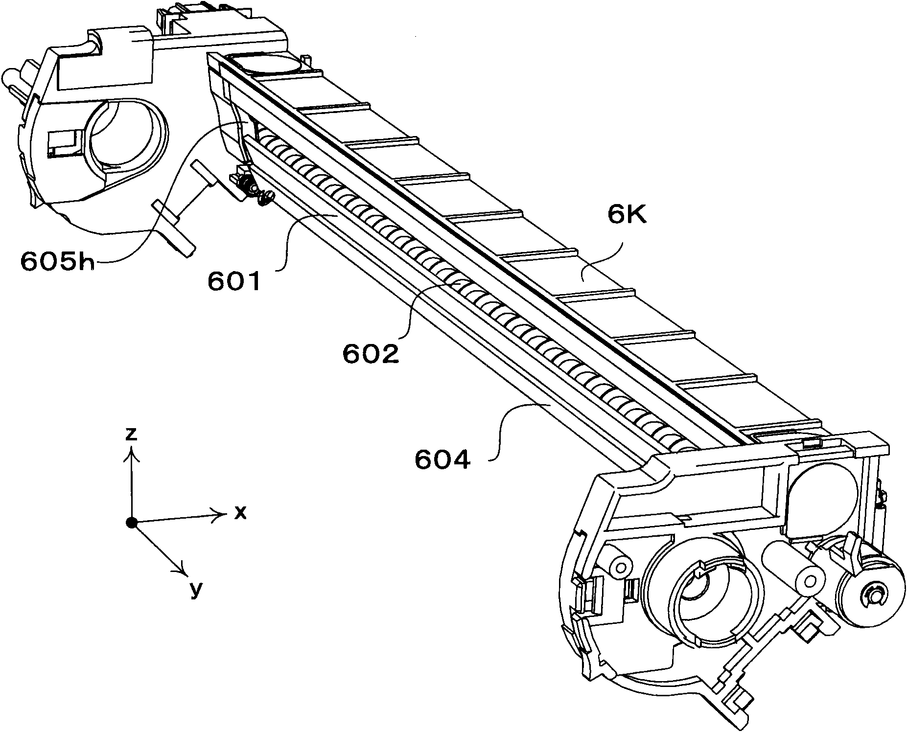
[0078] On the elastic sheet 603, a pattern of arranging a plurality of dots is screen-printed as the protrusions 603d.
[0079] By screen printing on the surface of the elastic sheet 603 to form Figure 9 The convex portion 603d of the printing pattern shown can ensure a gap corresponding to the thickness of the convex portion 603d between the cleaning blade 601 and the elastic sheet 603, and can prevent the cleaning blade 601 from coming into contact with the elastic sheet 603 (adhesion) . By forming the protrusion 603d bet...
no. 3 approach
[0087] Next, a third embodiment will be described. Hereinafter, parts having the same functions as those in the above-mentioned configuration examples are denoted by the same symbols, and description thereof will be omitted.
[0088] Conventionally, there is known a structure in which a secondary transfer unit that transfers a toner image from an intermediate transfer belt to a recording medium such as a sheet has a mechanism for supplying lubricating oil to a secondary transfer roller.
[0089] Such a secondary transfer unit includes a brush roller for supplying a lubricant, a solid lubricant, and a brush roller that pushes toward the brush roller with the front end of the brush in contact with the roller surface of the secondary transfer roller included in the secondary transfer unit. A spring that presses the lubricant, a bearing that fixes the rotating shaft of the brush roller, a case that holds the brush roller, and a drive gear that transmits rotational force from a dri...
PUM
 Abstract
Description
Claims
Application Information