Automatic ignition furnace and application method thereof

An automatic and stove technology, which is applied in the direction of combustion methods, combustion and ignition, household stoves/stoves, etc., can solve the problems of reducing the ignition speed of the ignition furnace and inconvenient use, and achieve the effect of fast ignition speed, easy ignition use, and good stability

Pending Publication Date: 2020-05-12
东莞市捷胜五金实业有限公司
View PDF0 Cites 0 Cited by
  • Summary
  • Abstract
  • Description
  • Claims
  • Application Information

AI Technical Summary

Problems solved by technology

[0004] The purpose of the present invention is to provide an automatic ignition furnace, which has the advantages of adding a fan for heat transmission, and the charcoal in the furnace burns quickly due to the effect of wind, and the ignition speed is fast, which is convenient for ignition, and solves the problem of ordinary ignition furnaces. After pouring the charcoal into the ignition furnace, igniting the ignition material, you have to wait patiently for half an hour or even longer before the charcoal is completely ignited, which reduces the ignition speed of the ignition furnace and is not convenient for people to use.

Method used

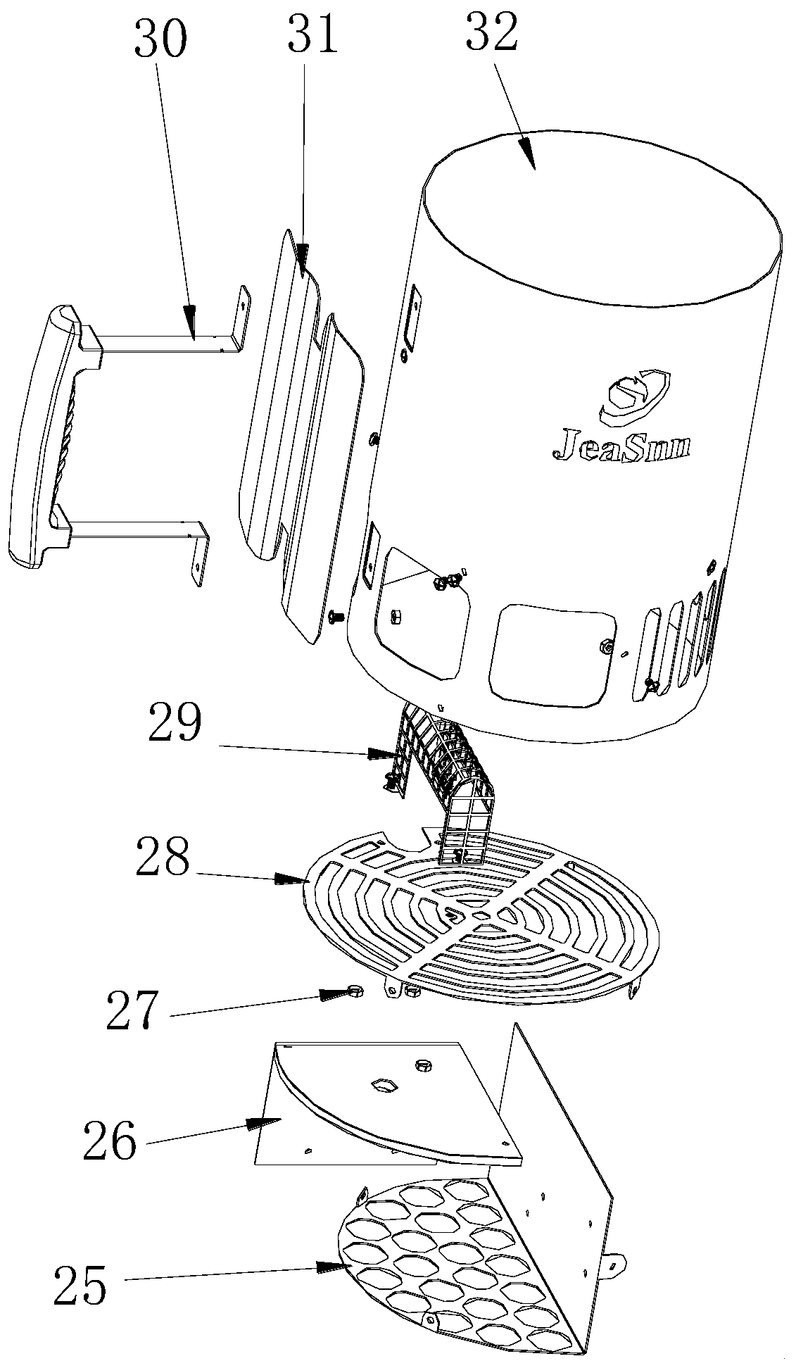

Image

  • Automatic ignition furnace and application method thereof
  • Automatic ignition furnace and application method thereof
  • Automatic ignition furnace and application method thereof

Examples


Embodiment Construction

[0021] The following will clearly and completely describe the technical solutions in the embodiments of the present invention with reference to the accompanying drawings in the embodiments of the present invention. Obviously, the described embodiments are only some, not all, embodiments of the present invention. Based on the embodiments of the present invention, all other embodiments obtained by persons of ordinary skill in the art without making creative efforts belong to the protection scope of the present invention.

[0022] In the description of the invention, it should be noted that the terms "upper", "lower", "inner", "outer", "front end", "rear end", "both ends", "one end", "another end" etc. The indicated orientation or positional relationship is based on the orientation or positional relationship shown in the drawings, and is only for the convenience of describing the present invention and simplifying the description, rather than indicating or implying that the referre...

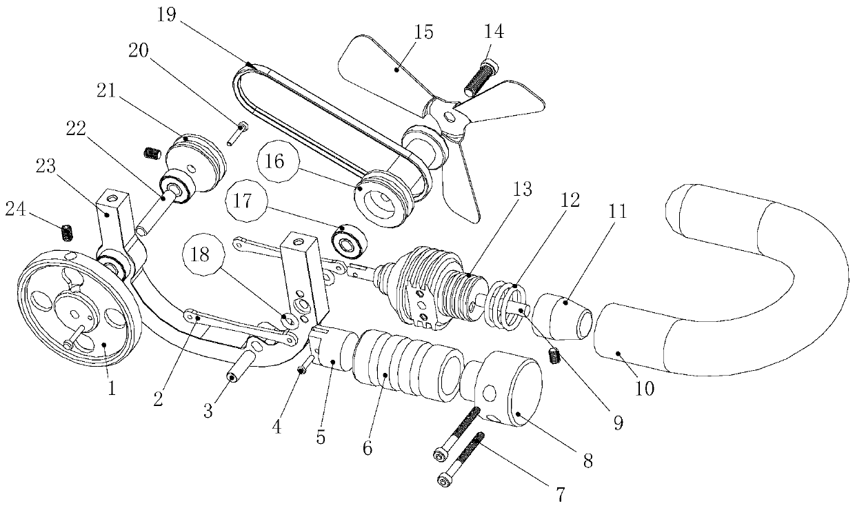

PUM


Abstract

The invention discloses an automatic ignition furnace and an application method thereof. The automatic ignition furnace comprises a transmission wheel, a first positioning pin and a furnace body. An inner cavity of the transmission wheel is fixedly connected with a bottom plate through a screw. The inner cavity of the transmission wheel is fixedly connected with a supporting plate. A thermal insulation layer is fixedly connected to the surface of the supporting plate through a screw and located at the bottom of the bottom plate. The surface of the supporting plate is fixedly connected with a support. The transmission wheel is movably connected to the bottom of the support. The top of the support is movably connected with a second fixing shaft. The surface of the second fixing shaft is sleeved with a flywheel. The automatic ignition furnace has the advantages that a heat transmission fan is additionally arranged, the combustion speed of charcoal in the furnace is fast increased under the effect of wind, the ignition speed is high, and the automatic ignition furnace is conveniently used for ignition; and the problems that when an ordinary ignition furnace is used, an ignition material is ignited after charcoal is poured into the ignition furnace, only after half an hour or even a longer time can all the charcoal be ignited, the ignition speed of the ignition furnace is decreased,and the ignition furnace is used by people inconveniently are solved.

Description

technical field [0001] The invention relates to the technical field of ignition furnaces, in particular to an automatic ignition furnace and a method for using the same. Background technique [0002] The types of stoves are usually divided according to the type of fuel: stoves that require pressurized fuel, stoves that do not need pressurized gas stoves, and stoves that require pressurized fuel. These stoves usually have a pump device that pumps air into the fuel bottle. In the middle, increase the pressure in the bottle, and then send the fuel into the burner. The multi-purpose stove can even be used for a variety of fuels, such as gasoline, kerosene, and stain-removing oil. If you choose gasoline as a fuel, it is best to use octane Low, unleaded gasoline is better, and the stove is a stove for heating and cooking; [0003] The pilot stove is a kind of stove. The ordinary pilot stove is to pour the charcoal into the pilot stove and ignite the fire starter. It takes half an...

Claims

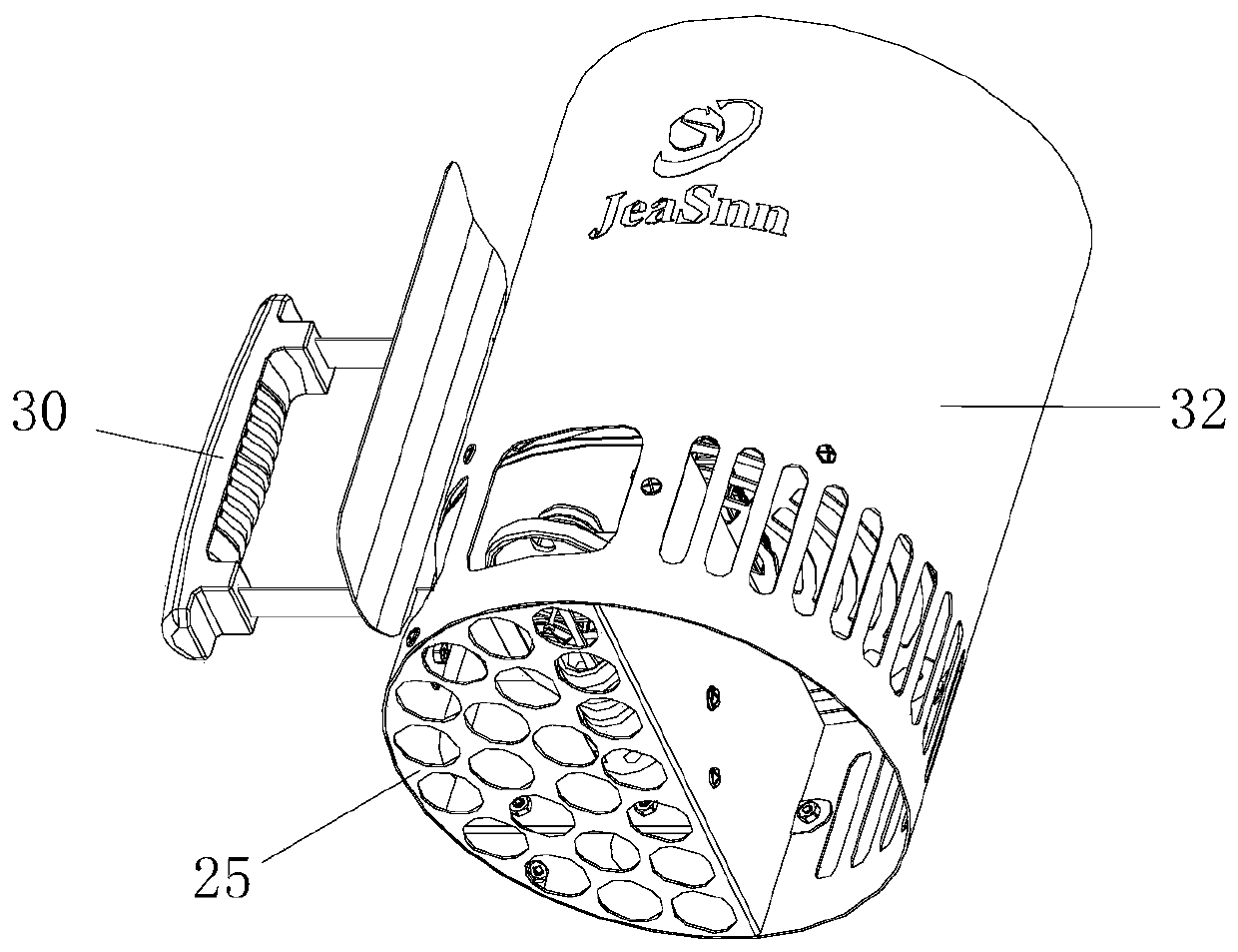

Application Information

Patent Timeline
Patent Type & Authority Applications(China)
IPC IPC(8): F24B1/00F23Q13/00
CPCF23Q13/00F24B1/00
Inventor 张兵立
Owner 东莞市捷胜五金实业有限公司
Why Eureka
Try Eureka