Power supply communication structure and lamp utilizing power supply communication structure

A technology of power supply and lamps, which is applied in the direction of discharge lamps, electric light sources, connections, etc., can solve the problems of easy-to-press wires, messy wires, electrification, etc., to prevent wires from being pressed and mis-connected wires, simple in structure, and safe to use Effect

Inactive Publication Date: 2010-12-01
OCEANS KING LIGHTING SCI&TECH CO LTD +1
View PDF0 Cites 8 Cited by
  • Summary
  • Abstract
  • Description
  • Claims
  • Application Information

AI Technical Summary

Problems solved by technology

[0002] Existing lamps generally include a light source part and an electrical part. The light source part includes a lamp holder and a light source. The electrical part includes a terminal connected to the lamp holder. The power connection of the lamp is generally realized by connecting wires and terminals. That is, the terminal is connected to the power supply, the light source is installed in the lamp cavity of the lamp holder, and the wire of the lamp holder is connected to the terminal to turn on the power supply to make the light source glow. In this power connection method, an additional switch needs to be installed on the wire to cut off the power supply Connect and extinguish the light source, and there are three major disadvantages in using this power connection method: 1. The wiring in the lamp cavity of the lamp holder is messy. If there are high-heating components in the lamp cavity, it is easy to damage the insulating layer of the wire and make the light source body charged. or a short circuit occurs; 2. It is easy to press the wire, and it is easy to press the wire during assembly. If it is a sealed structure, the wire will affect the overall structural performance of the lamp; Improvements have been made to the power connection of lamps

Method used


Image

  • Power supply communication structure and lamp utilizing power supply communication structure
  • Power supply communication structure and lamp utilizing power supply communication structure
  • Power supply communication structure and lamp utilizing power supply communication structure

Examples


Embodiment Construction

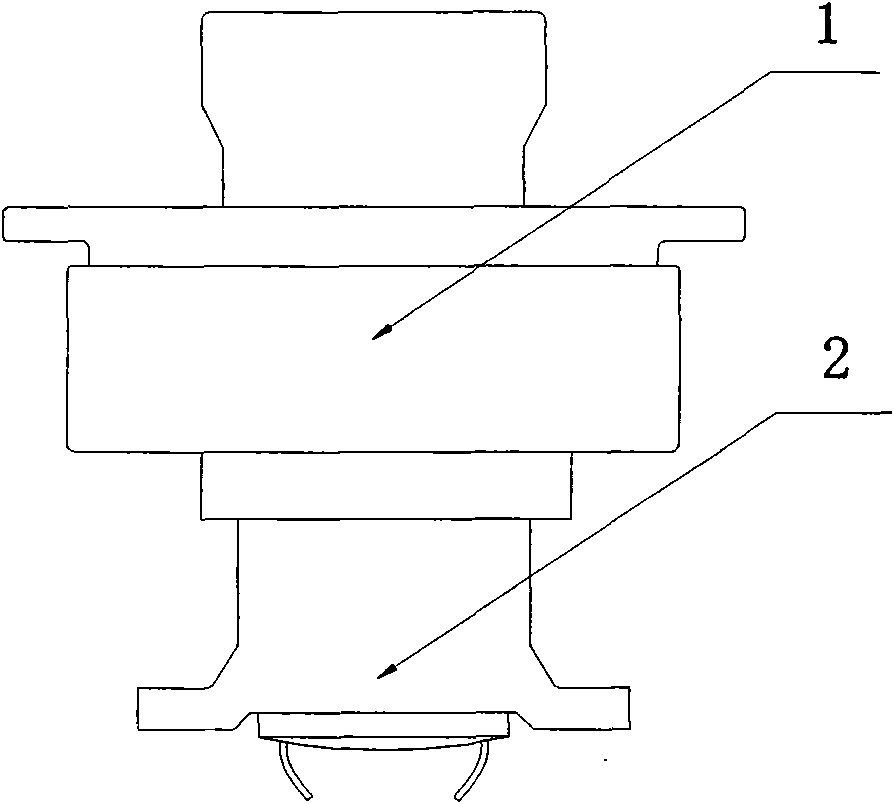
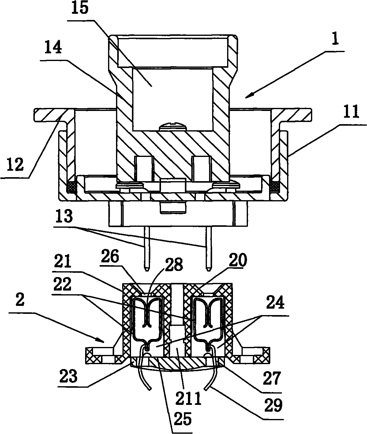
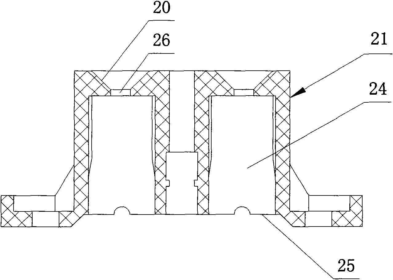
[0020] Such as figure 1 Shown is a combined schematic diagram of a preferred embodiment of the power connection structure of the lamp of the present invention, figure 2 shown, is figure 1 The disassembled cross-sectional view of the lamp of the present invention includes a light source part and an electrical part. It includes the electrical part housing and the terminal 2 provided on the electrical part housing for connecting the power supply. The lamp holder assembly 1 and the terminal 2 constitute the power connection structure of the lamp of the present invention. The main improvement of the present invention is that the The terminal 2 is provided with two conductive seats 22, and the two conductive seats 22 are respectively connected with wires 29 and connected to the positive and negative poles of the power supply (not shown) through the wires; the lamp holder assembly 1 is provided with two conductive sheets 13 The inner ends of the two conductive sheets 13 are respec...


PUM


Abstract

The invention relates to a power supply communication structure and a lamp utilizing the power supply communication structure. The power supply communication structure comprises a terminal and a lamp holder assembly, wherein two conducting seats are arranged in the terminal, and both of the conducting seats are respectively connected with lead wires and connected with the anode and the cathode of the power supply through the lead wires; the lamp holder assembly is provided with two conducting strips, and the inner ends of the two conducting strips are respectively connected with lead wires and connected with the anode and the cathode of a light source through the lead wires; and the lamp holder assembly and the terminal are plugged with the two conducting seats through the outer ends of the conducting strips so as to form a detachable connection. The lamp comprises a light source part and an electric part, wherein the light source part comprises the lamp holder assembly and the light source; the electric part comprises the terminal; and the light source part is connected with the electric part through a rotation shaft to form a rotatable connection which enables the conducting strips to be plugged in or out of the conducting seats correspondingly to switch on or off the light source. The power supply communication structure requires no lead wire for connection. The lamp has the advantages of simple structure and safe operation.

Description

technical field [0001] The invention relates to the field of lamps, more specifically, to a power connection structure and a lamp using the power connection structure. Background technique [0002] Existing lamps generally include a light source part and an electrical part. The light source part includes a lamp holder and a light source. The electrical part includes a terminal connected to the lamp holder. The power connection mode of the lamp is generally realized by connecting wires and terminals. That is, the terminal is connected to the power supply, the light source is installed in the lamp cavity of the lamp holder, and the wire of the lamp holder is connected to the terminal to turn on the power supply to make the light source glow. In this way of power connection, an additional switch needs to be installed on the wire to cut off the power supply Connect and extinguish the light source, and there are three major disadvantages in using this power connection method: 1. ...

Claims


Application Information

Patent Timeline
Patent Type & Authority Applications(China)
IPC IPC(8): H01R33/05H01R33/94F21S2/00F21V23/06
Inventor 周明杰宋明松
Owner OCEANS KING LIGHTING SCI&TECH CO LTD
Why Eureka
Try Eureka