Access node switching method

A technology for accessing nodes and nodes, applied in connection management, wireless communication, electrical components, etc., can solve the problems of no application configuration, the destination node does not implement higher layers, etc., to achieve the effect of increasing the waiting time

Active Publication Date: 2010-12-08
FRANCE TELECOM SA
View PDF3 Cites 0 Cited by
  • Summary
  • Abstract
  • Description
  • Claims
  • Application Information

AI Technical Summary

Problems solved by technology

While said expectation certainly reduces latency, it does not improve the quality of service of one or more applications in use, e.g. by increasing the offered bit rate, because the destination node does not implement higher All possible application configurations for using services in conjunction with telecommunication entities
Although this possible application configuration information can exist eg in some intermediate nodes in the IMS (IP Multimedia Subsystem) architecture, it requires the use of additional signaling messages

Method used


Image

  • Access node switching method
  • Access node switching method
  • Access node switching method

Examples


Embodiment Construction

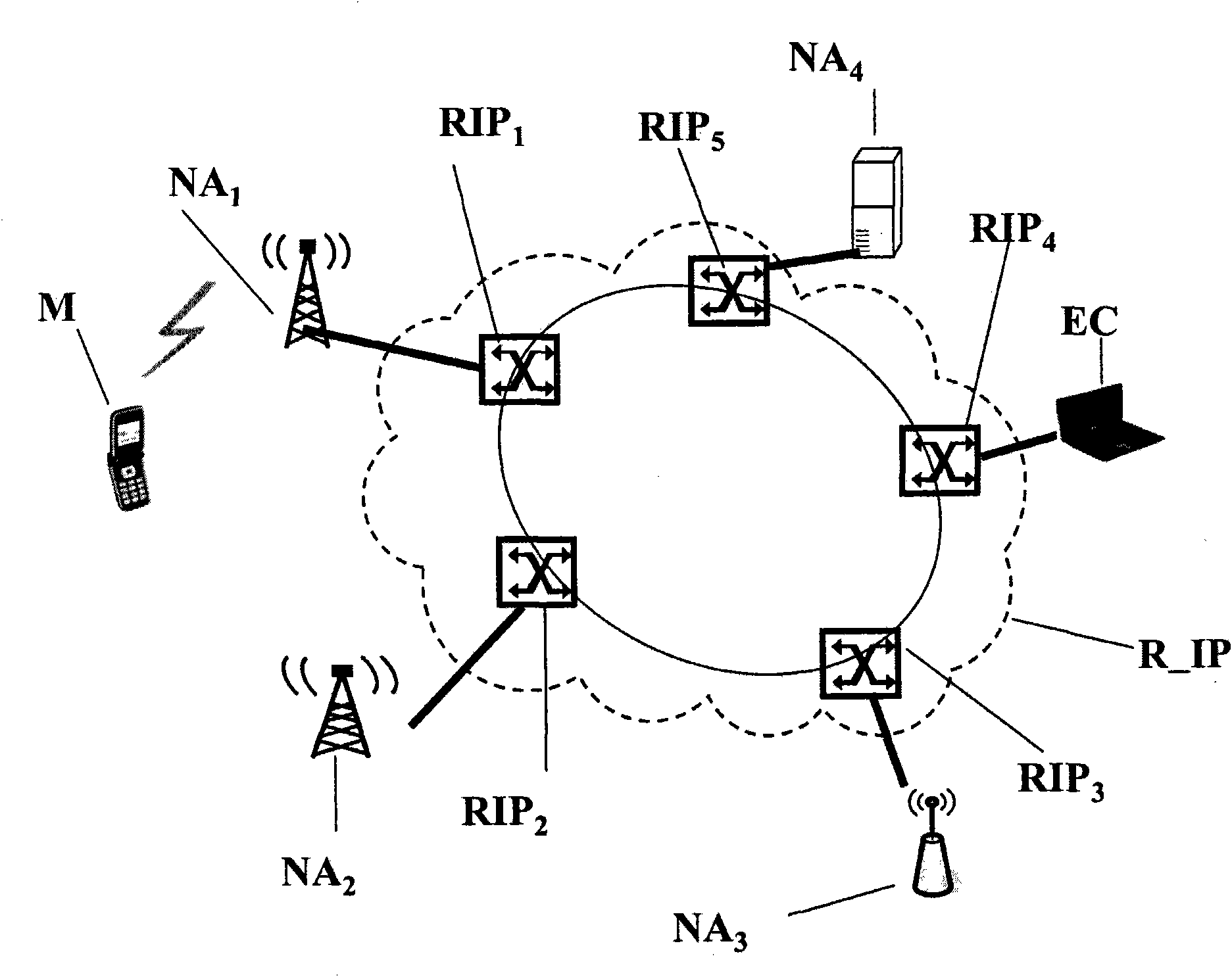
[0063] figure 1 shows the connection to the access node NA used to set up the 1 Telecommunications network architecture for communication between a terminal M of and a communication entity EC connected to the packet-switched network R_IP, said communication entity EC providing services to the terminal M via the packet-switched network. Although only one communicating entity is shown in this figure for the sake of clarity, obviously there may be more than one communicating entity.

[0064] The communication network includes a plurality of access nodes. The access nodes may be in the same access network or in different access networks. For clarity, in figure 1 The access network is not shown. exist figure 1 , as a non-limiting illustrative example, the access node NA 2 Is the base station of the UMTS cellular mobile network, the access node NA 3 is the access point of the WiMAX wireless network, and the access node NA 4 It is the access point of FTTH cable network.

[0...


PUM


Abstract

Method of switching an original access node (NAi) to a destination access node (NA2, NA3, NA4) of a terminal (M) during implementation of at least one service with at least one remote communicating entity (EC) through a packet switching network (RJP), the terminal, connected to the original access node, being associated with a first communication context and with a set of possible application configurations for the implementation of the relevant service, a communication context containing parameters relating to so-called ''low'' layers and parameters relating to so-called ''high'' layers defining a given application configuration, the layers being defined by a communication model, the method comprising a step (E2, E3) of discovering potential destination access nodes, a step (E4) of selecting, by the original access node, one of the potential destination nodes, and a step (E5) of transferring the first communication context of the terminal from the original access node to the selected destination access node.

Description

technical field [0001] The field of the invention is the field of telecommunications, and more specifically, the field of mobile radio communication networks. [0002] The invention more particularly relates to switching an access node of a terminal while the terminal is using one or more services in conjunction with one or more telecommunication entities via a packet-switched network. The terminal is initially connected to the source access node and is associated with a current communication context containing information about the layers of the communication model required for using each of the relevant services in conjunction with the communicating entity relevant. Because of the terminal's mobility, the terminal may need to be handed over from the source access node to the destination access node. Background technique [0003] Note that the source and destination access nodes may be in the same access network or in different access networks. These access networks may ...

Claims


Application Information

Patent Timeline
Patent Type & Authority Applications(China)
IPC IPC(8): H04W36/08H04W76/22
CPCH04W36/08H04W76/041H04W76/22
Inventor 菲利普·赫伯林卡迪杰·道德特里基杰尔姆·庞斯
Owner FRANCE TELECOM SA
Why Eureka
Try Eureka