
Single-piece feeding device, embroidering, sewing or quilting machine comprising the device, and method for embroidering on a single-piece

A feeding device and single-piece technology, applied in sewing machine components, embroidery machine mechanisms, automatically controlled embroidery machines, etc., can solve the problems of constant movement in a specific direction and limited relative movement, and achieve the effect of saving time.

Inactive Publication Date: 2010-12-15
LAESSER AG
View PDF8 Cites 3 Cited by
  • Summary
  • Abstract
  • Description
  • Claims
  • Application Information

AI Technical Summary

Problems solved by technology

The disadvantage of the aforementioned device is that the embroidery base must always be moved in a very specific direction, in this case downwards, in order to guide the decoration away from the guiding means
Therefore, after the ornaments are embroidered on the embroidery base cloth, the relative movement between the equipment and the base cloth will become very limited

Method used


Image

  • Single-piece feeding device, embroidering, sewing or quilting machine comprising the device, and method for embroidering on a single-piece
  • Single-piece feeding device, embroidering, sewing or quilting machine comprising the device, and method for embroidering on a single-piece
  • Single-piece feeding device, embroidering, sewing or quilting machine comprising the device, and method for embroidering on a single-piece

Examples


Embodiment Construction

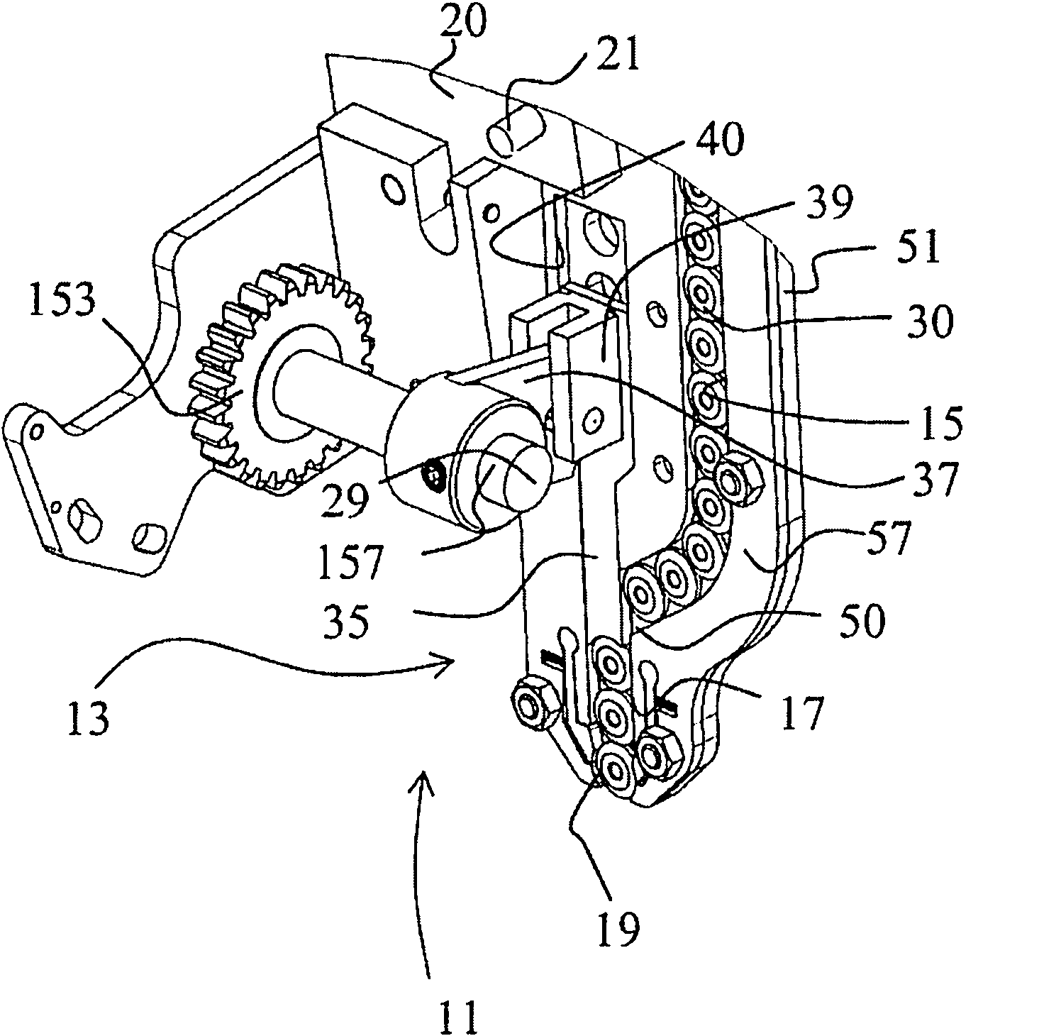
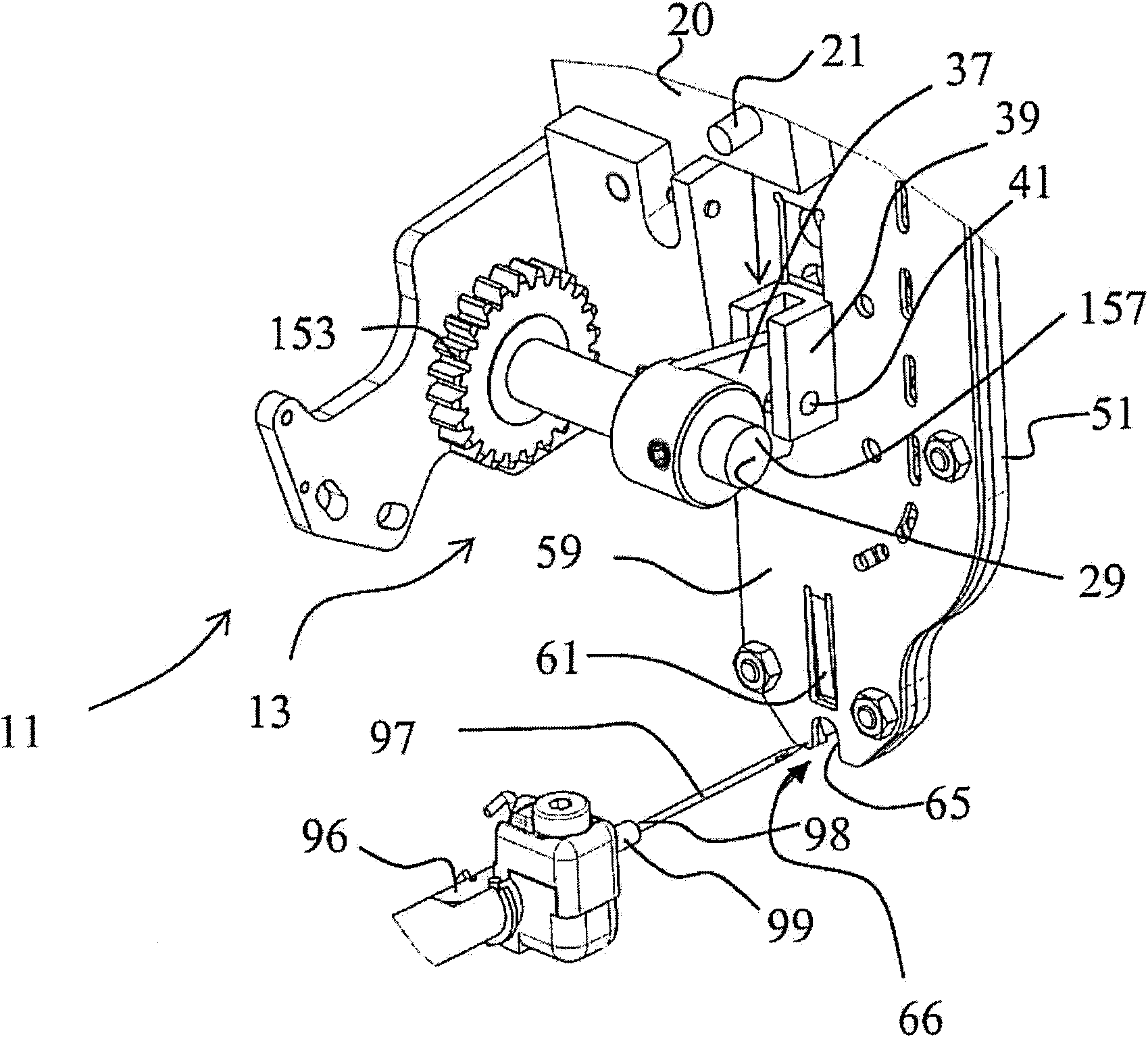
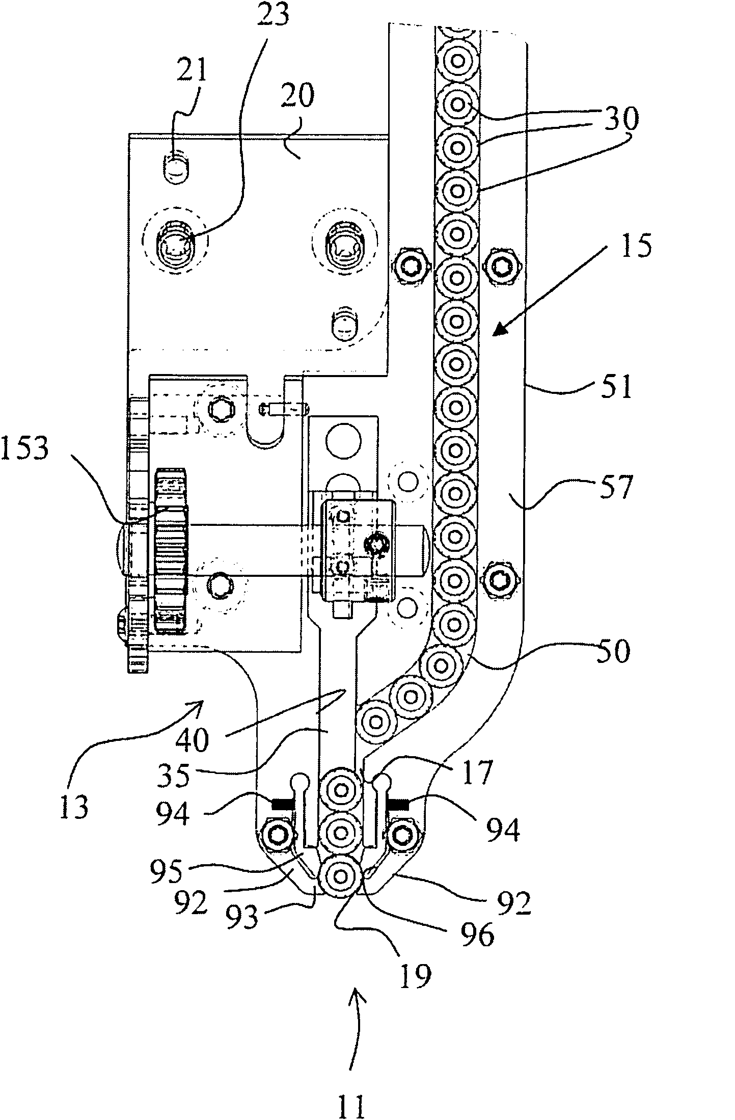
[0054] The exemplary embodiments described below are designed to be driven with the drive of a sewing or embroidery machine. The drive can be driven by a geared shaft 3, or a sprocket shaft ( Figure 4 ). The shaft 3 can extend the entire length or part of the length of the embroidery machine and can be driven to rotate in either direction by a motor (not shown).

[0055] According to the invention, the switching of the drive means can be controlled in a switch arrangement or coupling means in the single-piece feeding device, as disclosed, for example, in patent EP 1 764 434. The content of patent EP1 764 434 has been incorporated into the present specification by reference. This known switch structure, which is not part of the present invention, enables items such as small metal pieces or ribbon guides to be connected by needle tappets.

[0056] The main components of the feeding structure 13 of the single-piece feeding device according to the present invention are a feeding...


PUM


Abstract

The invention relates to a single-piece feeding device (9) used in embroidering, sewing or quilting machine, which comprises a front part (11) with the back (12) facing the embroidery base cloth (67) to clamping a single-piece (30) at a correct position to embroidering the single-piece on the embroidery base cloth (67); the front part (11) can comprise a box (15), a single-piece clamper (19) and a feeding structure (13); the box (15) has an inner space for containing a plurality of single-piece for embroidery; the single-piece clamper (19) is used for fixing a single-piece (30) at a position; the feeding structure (13) is configured to move one of the single-pieces (30) in the box (15) to the single-piece clamper (19) along a feeding path (17) by a conveying motion by power. The apparatus is characterized in that: the single-piece clamper (19) has an outlet (91) for limiting the single-piece (30) to move to its back side (12) only, thereby the single-piece (30) has no option but to leave the single-piece clamper (19) by the outlet (91) direction. The invention also relates to an embroidering machine comprising the device, especially a shuttle embroidering machine.

Description

technical field [0001] The present invention relates to a single-piece feeding device according to claim 1 for feeding a single piece to a sewing site of an embroidery, sewing or quilting machine, an embroidery, sewing or quilting machine comprising the device, and an embroidery, sewing or quilting machine according to claim 1 14. A method of embroidering a single piece of claim 13. Background technique [0002] In the following description, the term embroidery machine should be understood as embroidery, sewing, quilting and small embroidery machines. The device is especially designed for shuttle embroidery machines with a plurality of needles in one needle thread. Such devices are known, for example, for embroidery machines for preparing small metal pieces, lace and the like so that they can be sewn on an embroidery base by means of needles and threads. [0003] In the prior art there are so-called small sheet metal guides, eg EP-A 1 561 849. By means of these small shee...

Claims


Application Information

Patent Timeline
IPC IPC(8): D05B35/06D05B3/22D05C7/08
CPCD05D2303/12D05C7/08D05B3/22
Inventor F·拉泽
Owner LAESSER AG
Learn More