Supercharge Your Innovation With Domain-Expert AI Agents!

Hinge device

A hinge device and hinge technology, which is applied to hinges with pins, door/window accessories, wing fan parts, etc., can solve the problems of high cost, difficulty, and many installation screws, etc., to reduce the number of parts, cost reduction, The effect of easy installation work

Inactive Publication Date: 2010-12-15
TAKIGEN MFG CO LTD
View PDF4 Cites 0 Cited by
  • Summary
  • Abstract
  • Description
  • Claims
  • Application Information

AI Technical Summary

Problems solved by technology

[0004] However, in the above-mentioned existing hinge device, since the hinge base on the housing side is installed on one side of the fixed frame on the front of the housing by welding or mounting screws, the hinge blade on the door side is installed on the door by welding or mounting screws. There is a problem that the installation work of these hinge parts is complicated and difficult.
In addition, when these hinge bases and hinge blades are all mounted with mounting screws, a large number of mounting screws are required as a whole, resulting in an increase in the number of parts and a problem of high cost.

Method used


Image

  • Hinge device
  • Hinge device
  • Hinge device

Examples


Embodiment Construction

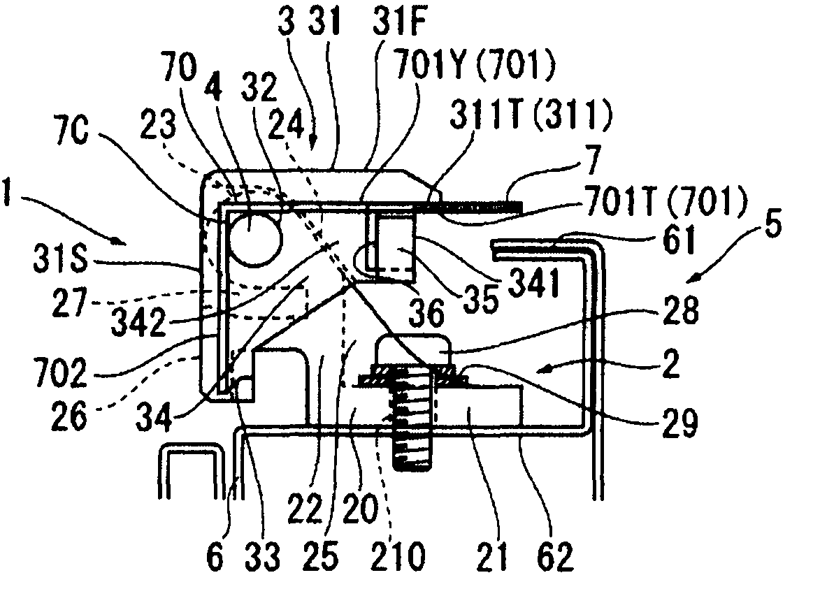
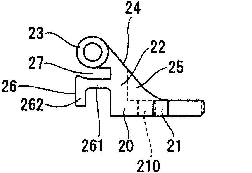
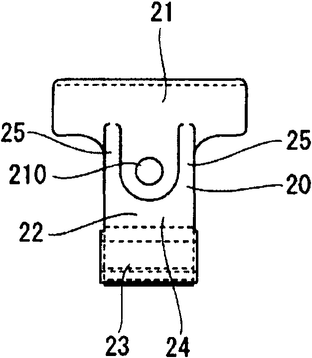
[0071] Next, an embodiment for carrying out the present invention will be described with reference to the drawings. figure 1 Indicates a shelf for storing electrical and electronic equipment and other various equipment, and a hinge device used on the shelf. Such as figure 1 As shown, such a shelf 5 is composed of a casing 6 and a door 7 as described above, the front of the casing 6 is provided with a fixed frame 61, and one side of the door 7 relative to the pivoting side of the casing 6 is bent form a free edge at approximately right angles. The hinge device 1 is composed of the following parts: the hinge base 2 on the side of the casing, which is installed on a side portion 62 of the fixed frame 61 on the front of the casing 6; the hinge blade 3, which corresponds to the above-mentioned hinge base 2 , and is mounted on a corner portion 7C of one side inside the door 7 ; and a hinge pin 4 that connects the hinge base 2 and the hinge blade 3 .

[0072] In the above hinge ...


PUM


Abstract

This device 1 has the hinge blade 3 composed of a blade body 31, a pin insertion hole 32, a pair of locking claws 33, 33, a positioning-fixing part 34 and stoppers 35, 35. When the hinge blade 3 is mounted to the door 7, the pair of locking claws 33, 33 of the blade body 31 are locked to both sides of a slit starting edge of a notch 70 (of the door 7) to fit and attach the blade body 31 onto the notch 70. The stoppers 35, 35 of the blade body 31 are brought into pressure contact with the inner surface of the door 7 to mount and fix the hinge blade 3 to the door 7.

Description

technical field [0001] The present invention relates to a hinge device, and more particularly to a hinge device used for a shelf or the like for storing electrical and electronic equipment and other various equipment. Background technique [0002] In general, a shelf for storing electrical and electronic equipment and the like is composed of a housing and a door, and the door is usually attached to the front of the housing through a plurality of hinges (devices) so as to be openable and closable. In this rack, the front of the cabinet is provided with a fixed frame, and one side portion of the door relative to the pivoting side of the cabinet is bent at approximately a right angle to form a free edge, forming a box shape. The hinge device used for this shelf is composed of the following parts: a hinge base on the side of the cabinet, which is installed on (one side of) the fixed frame of the cabinet; a hinge blade on the side of the door, which is connected to The hinge bas...

Claims


Application Information

Patent Timeline
Patent Type & Authority Applications(China)
IPC IPC(8): E05D3/02E05D7/04E05D5/10E05D5/02
CPCE05D3/02E05D7/1077E05Y2600/622E05Y2900/132
Inventor 濑川志朗
Owner TAKIGEN MFG CO LTD
Features
  • R&D
  • Intellectual Property
  • Life Sciences
  • Materials
  • Tech Scout
  • Unparalleled Data Quality
  • Higher Quality Content
  • 60% Fewer Hallucinations
Learn More