
All-fiber current transformer and working method thereof

A current transformer and all-fiber technology, applied in the direction of voltage/current isolation, etc., can solve serious problems, temperature effects, poor temperature stability of the system, etc., and achieve the effects of improving sensitivity, eliminating birefringence, and improving phase sensitivity

Inactive Publication Date: 2010-12-15
SHANGHAI BOOM FIBER SENSING TECH
View PDF0 Cites 26 Cited by
  • Summary
  • Abstract
  • Description
  • Claims
  • Application Information

AI Technical Summary

Benefits of technology

This patented technology describes a new design for a type of electricity sensor called an All Fiber Current Transformer (AFCT). It allows two different types of light waves with opposite phases to travel through them simultaneously, resulting in improved detection capabilities even if there's some slight differences between these waveforms due to ambient conditions or other influences like pressure variations. Additionally, its use eliminates the problem of randomly oriented polarized states caused by the rotation of the crystal inside itself. Overall, this innovation provides technical benefits including increased efficiency, reduced noise levels, better performance during extreme weather situations, enhanced resistance against damage, and more reliable operation than previous methods.

Problems solved by technology

This patented technical problem addressed by this patents relates to improving the performance (efficacy) or reliability of an optofluidic flowmeter that uses fibre technology instead of conventional electricity conductor materials like copper wires due to its better resistance against external factors like heat and vibration compared to other types of material. Additionally, the use of specialized components can improve their durability without compromising signal quality.

Method used


Image

  • All-fiber current transformer and working method thereof
  • All-fiber current transformer and working method thereof
  • All-fiber current transformer and working method thereof

Examples


Embodiment Construction

[0036] The present invention provides an all-optical fiber current transformer, and the specific implementation manner of the present invention will be described in detail below with reference to the accompanying drawings.

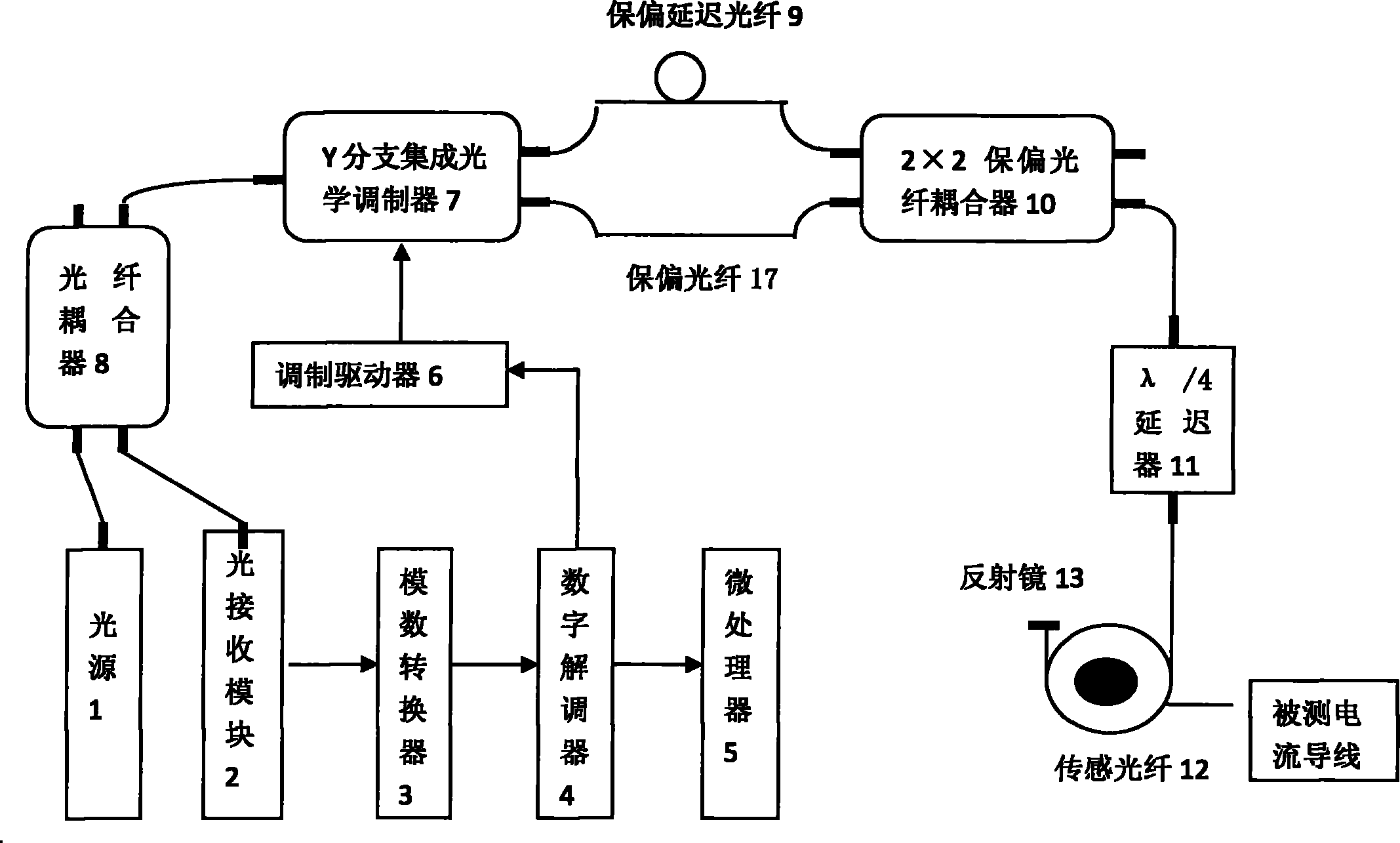
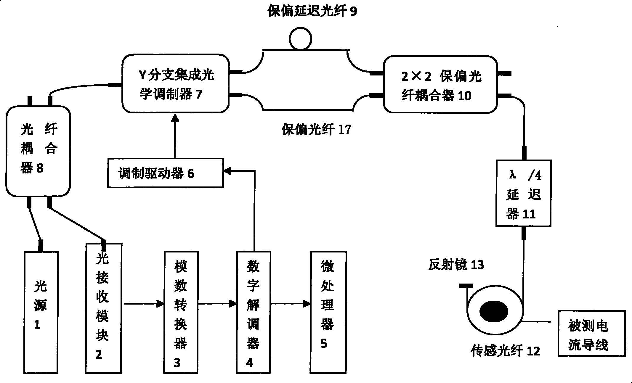
[0037]An all-fiber current transformer, comprising a light source 1, an optical receiving module 2, an analog-to-digital converter 3, a digital demodulator 4, a microprocessor 5, a modulation driver 6, a Y branch integrated optical phase modulator 7, and a fiber optic coupler 8. Composed of polarization maintaining delay fiber 9, polarization maintaining fiber 17, polarization maintaining fiber coupler 10, λ / 4 delayer 11, sensing fiber 12 and reflector 13. The connection method is: the optical output end of the light source 1 is input to the first input end of the fiber coupler 8, the light receiving module 2 is connected to the second input end of the fiber coupler 8, the light receiving module 2, the digital converter 3, the digital solution The modulato...


PUM


Abstract

The invention discloses an all-fiber current transformer and a method thereof, aiming to overcome the defects that a traditional electromagnetic current transformer is easily subjected to electromagnetic interference and has complicated insulation structure, magnetic saturation existence and the like. The technical scheme of the invention comprises the following steps of: demodulating light output by a light source into X-axis polarized light and Y-axis polarized light by a Y-branch integrated optical phase modulator; converting into sinistral circular polarized light and dextral circular polarized light in a lambda/4 retarder; generating a magnetic field by a current in a lead due to the faraday effect; returning the two beams carrying faraday effect phase information to the Y-branch integrated optical phase modulator to intervene when beams in optical fiber is transmitted around the lead; and enabling an interference result to enter a subsequent treatment system from the optical fiber coupler to acquire the faraday effect phase information at the measuring point. The invention avoids the hidden danger of ferromagnetic resonance and magnetic saturation by adopting the optical fiber as a sensing medium and has a series of advantages of high detection accuracy, good environmental suitability, and the like.

Description


Claims


Application Information

Patent Timeline
Owner SHANGHAI BOOM FIBER SENSING TECH
Learn More