Monitoring and detecting device on stirring tank

A detection device and stirring tank technology, applied in the direction of instruments, computer control, simulators, etc., can solve the problems of inability to spot inspection of stirring tanks, and achieve the effect of eliminating potential safety hazards and improving work efficiency.

Active Publication Date: 2012-02-08
YUNNAN DAHONGSHAN PIPELINE
View PDF0 Cites 0 Cited by
  • Summary
  • Abstract
  • Description
  • Claims
  • Application Information

AI Technical Summary

Problems solved by technology

[0003] The purpose of the present invention is to provide a monitoring and detection device on the stirring tank, which can solve the problem that the stirring tank cannot be safely and effectively inspected in thunderstorm days

Method used


Image

  • Monitoring and detecting device on stirring tank
  • Monitoring and detecting device on stirring tank
  • Monitoring and detecting device on stirring tank

Examples


Embodiment Construction

[0022] Below in conjunction with accompanying drawing, the present invention will be further described.

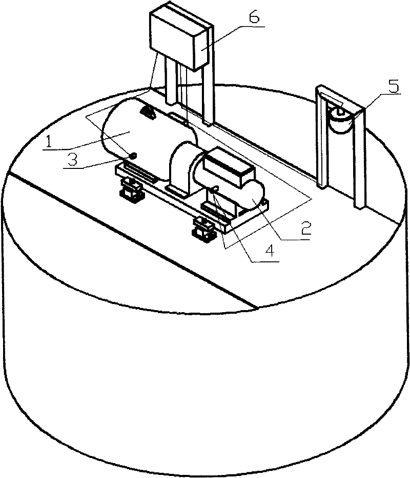
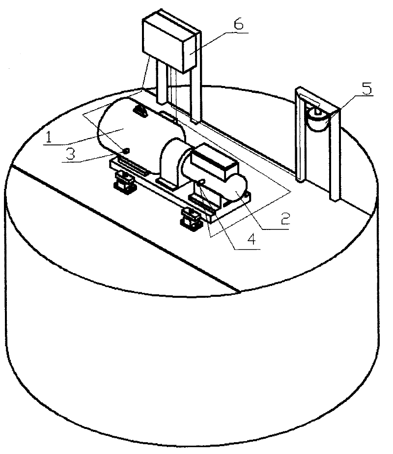
[0023] Such as figure 1 As shown, the monitoring and detection device of the present invention includes a motor temperature detector 3 , a reducer temperature detector 4 , a video acquisition device 5 and a junction box 6 .

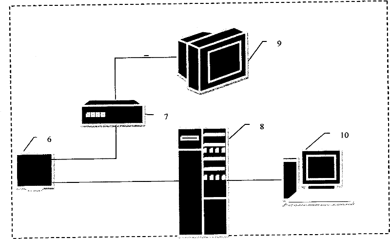
[0024] Such as figure 1 As shown, the video acquisition device 5 is installed on the top of the stirring tank through a bracket about 1.5 meters high. In order to collect the information of each corner in the stirring tank, the video acquisition device adopts a video acquisition device that can rotate and collect in all directions, and the video signal passes through After the junction box 6 is sent to the central control room switch 7, it is directly fed back on the pumping station video monitor 9 (such as figure 2 shown).

[0025] The two temperature detectors 3 and 4 adopt PT100 thermal resistance temperature sensors, which are respectively ins...


PUM


Abstract

The invention discloses a monitoring and detecting device on a stirring tank. The device comprises a motor temperature detector (3), a decelerator temperature detector (4), a video acquisition device (5) and a connection box (6), wherein the video acquisition device (5) is arranged at the top of the stirring tank to monitor the running condition of the stirring tank; and the motor temperature detector (3) and the decelerator temperature detector (4) are arranged on a stirring tank motor (1) and a decelerator (2) respectively and used for detecting the temperatures of the stirring tank motor (1) and the decelerator (2). The device eliminates great potential safety hazard when a worker goes to the top of the stirring tank in thunderstorm days, and improves the work efficiency of point inspection.

Description

technical field [0001] The invention belongs to the field of slurry pipeline transportation, in particular to a monitoring and detection device on a stirring tank. Background technique [0002] During the pipeline transportation of slurry, due to various reasons, the slurry will be temporarily stored in the stirring tank, or the incoming slurry needs to enter the stirring tank before being transported to the next stage. The height of the currently used stirring tank itself is 12 meters, plus other auxiliary facilities, its height will exceed 15 meters. However, the pump station is located in a minefield, and the mixing tank is a tall building in the station. It is a great safety hazard to go to the mixing tank for inspection during thunderstorms. Moreover, with the increase of the transmission output, the mixing tank is always in operation. When the thunderstorm season comes, due to the existence of the above problems, it is difficult to grasp the operation of the mixing ta...

Claims


Application Information

Patent Timeline
Patent Type & Authority Patents(China)
IPC IPC(8): G05B19/048
Inventor 李锐安建普光跃黄朝兵胡国庆张洪瑜赵承宗杨何军余敏张贤照
Owner YUNNAN DAHONGSHAN PIPELINE
Why Eureka
Try Eureka