Improved chemical vapor-phase deposition method by uisng graphite heating furnace as hot source

A technology of chemical vapor deposition and graphite heating furnace, applied in gaseous chemical plating, metal material coating process, coating, etc., can solve problems such as increasing equipment investment and operating costs, affecting transmission system windows, and hidden dangers of hydrogen safety , to achieve the effects of reduced attenuation, increased deposition rate, and enlarged reaction area

Inactive Publication Date: 2002-06-19
YANGTZE OPTICAL FIBRE & CABLE CO LTD
View PDF0 Cites 0 Cited by
  • Summary
  • Abstract
  • Description
  • Claims
  • Application Information

AI Technical Summary

Problems solved by technology

[0004] First, when the concentration of hydrogen in the air reaches a certain limit, an explosion will occur, and long-term use of hydrogen will pose a huge safety hazard;
[0005] Second, hydrogen combustion will generate a large amount of heat and exhaust gas. In order to maintain the temperature and humidity of the operating environment, these exhaust gases need to be pumped and treated, which will increase the corresponding equipment investment and operating costs.
This will affect the window of the transmission system near 1385nm, as well as adversely affect the transmission performance of other operating bands (such as 1310nm to 1550nm)

Method used


Image

  • Improved chemical vapor-phase deposition method by uisng graphite heating furnace as hot source
  • Improved chemical vapor-phase deposition method by uisng graphite heating furnace as hot source
  • Improved chemical vapor-phase deposition method by uisng graphite heating furnace as hot source

Examples


Embodiment 1

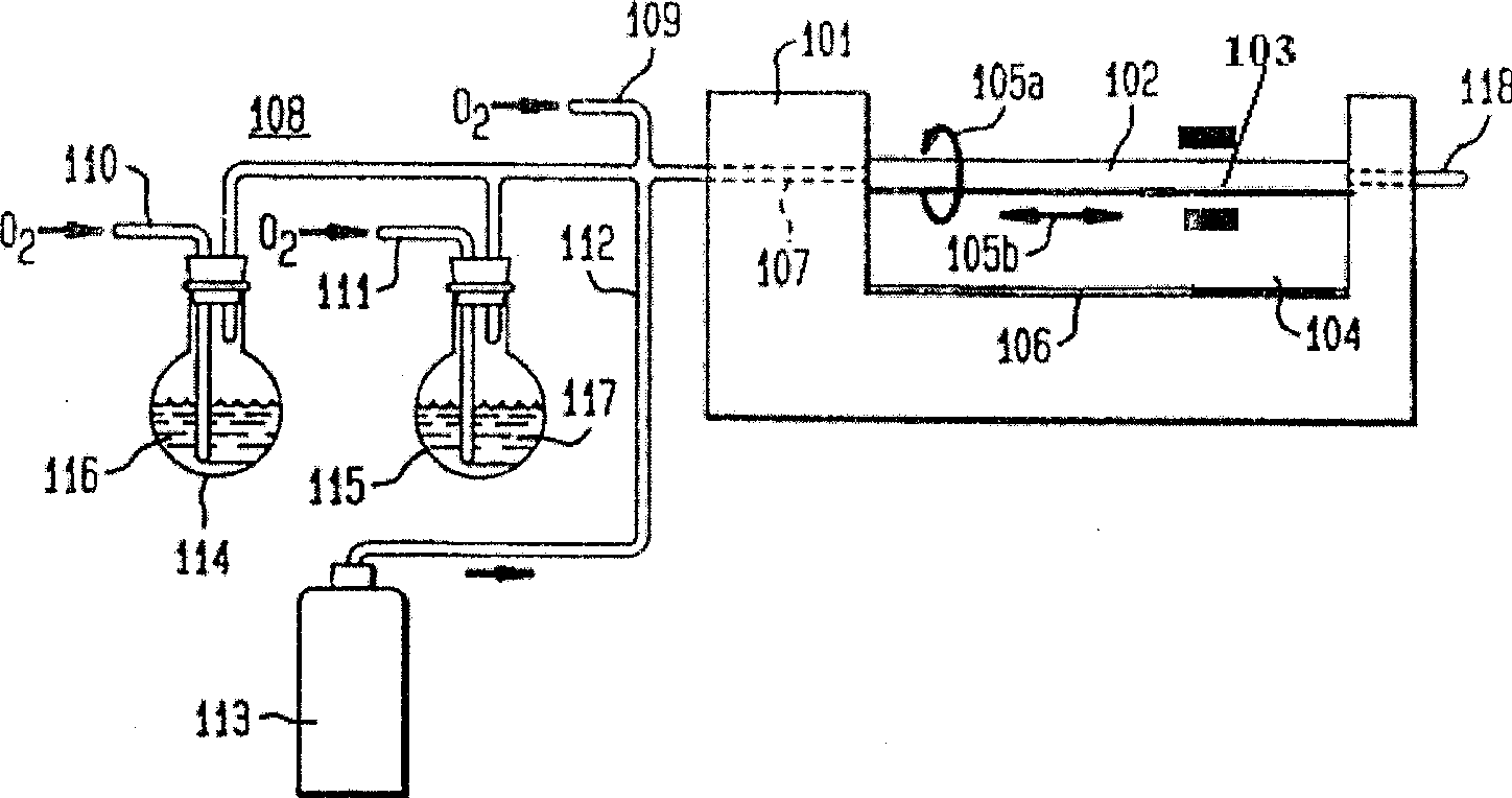
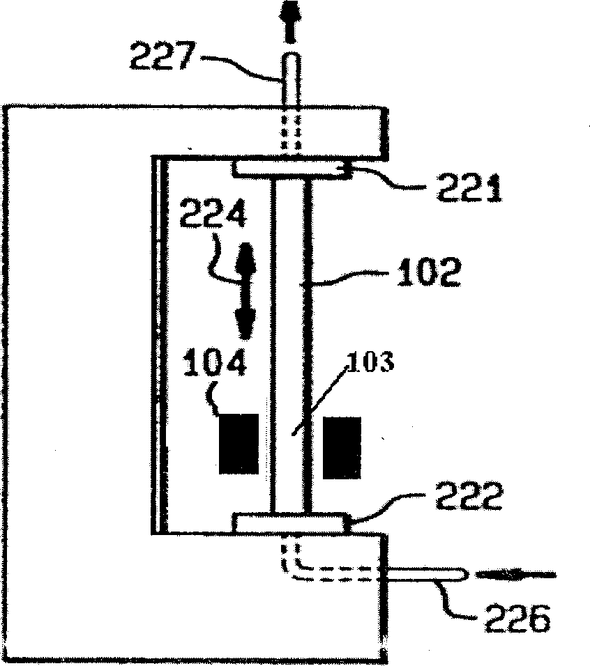
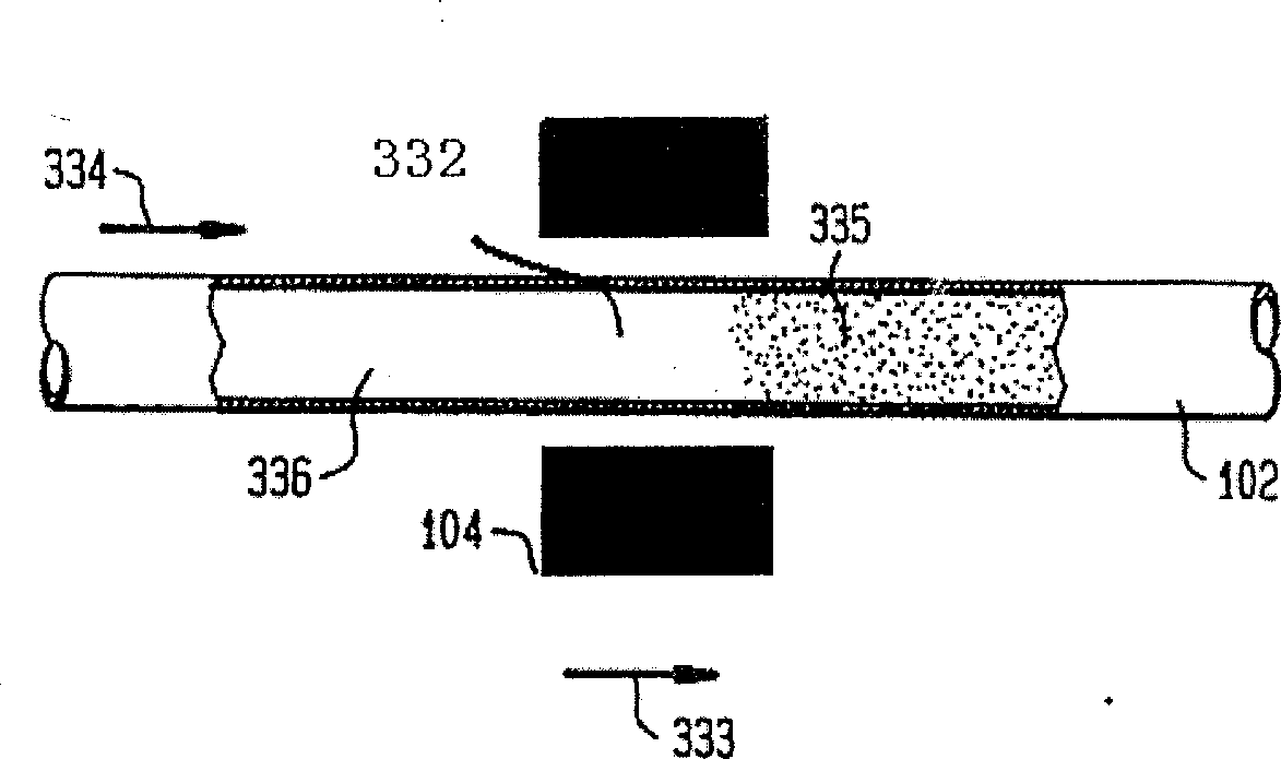
[0018] Such as figure 1 As shown, a quartz liner 102 for deposition reaction is fixed horizontally on the MCVD bed 101 . There is a heated area 103 inside the quartz liner, and the heat of the heated area is generated by a heating medium 104 . The heating equipment of the present invention is a graphite resistance heating furnace, a tubular heating furnace with graphite components as heating elements and graphite components or others as bushings. During the deposition and rod forming process, the quartz liner is located in the central part of the graphite resistance heating furnace; and it is continuously rotating, as shown by the rotation arrow 105a in the figure. As mentioned above, the heated zone 103 of the quartz liner is heated by a graphite resistance heating furnace fixed to a screw drive unit 106 . The screw driving device 106 can horizontally move back and forth on the MCVD bed at a constant speed; thereby driving the graphite resistance heating furnace to move bac...

Embodiment 2

[0025] Another embodiment of the present invention is to change the graphite resistance heating furnace in Example 1 into a graphite induction heating furnace, and other operations are the same.


PUM


Abstract

The present invention is characterized by that it uses graphitc heating furnace us heaitng source and adopts improved chemical vapor deposition process to prepare optical fiber preform. Said invented produce incldues the following steps: A. using raw materials to produce deposition reaction to obtain deposit lining tube; and B. melt-condensing the deposit lining tube into solid core rod. Said invention can improve performance of otpical fiber preform, and improve performance of optical fiber, and can raise deposition rate and can save cost of equipment and operation. The invention avoids hidden safe trouble since hydrogen used in traditional technique.

Description

technical field [0001] The invention relates to a method for manufacturing an optical fiber prefabricated rod, in particular to a method for manufacturing an optical fiber prefabricated rod by an improved chemical vapor deposition method using a graphite heating furnace as a heat source. Background technique [0002] At present, the process method used to manufacture commercial silica optical fiber is mainly chemical vapor deposition method, which is divided into in-tube method and out-of-tube method. For the out-of-tube method, the main process methods are two kinds of out-of-tube vapor deposition method and axial phase vapor phase deposition method, while the in-tube method mainly includes two kinds of plasma chemical vapor deposition method and improved chemical vapor phase deposition method. The improved chemical vapor deposition method, or MCVD method, is a classic process developed by Mache8ney and others at AT&T Bell Laboratories in the United ...

Claims


Application Information

Patent Timeline
Patent Type & Authority Applications(China)
IPC IPC(8): C23C16/46
Inventor 何珍宝程铭张穆
Owner YANGTZE OPTICAL FIBRE & CABLE CO LTD
Why Eureka
Try Eureka