Heat exchanger

A technology for heat exchangers and heat transfer surfaces, applied in the direction of heat exchange equipment, heat exchanger types, indirect heat exchangers, etc., to achieve the effects of improving flow characteristics, improving support, and reliable sealing

Active Publication Date: 2010-12-15
ALFA LAVAL CORP AB
View PDF4 Cites 12 Cited by
  • Summary
  • Abstract
  • Description
  • Claims
  • Application Information

AI Technical Summary

Problems solved by technology

Therefore, there is

Method used


Image

  • Heat exchanger
  • Heat exchanger
  • Heat exchanger

Examples


Embodiment Construction

[0036] The embodiments of the present invention with further improvements described below are merely regarded as examples, and are in no way intended to limit the scope of protection set by the claims.

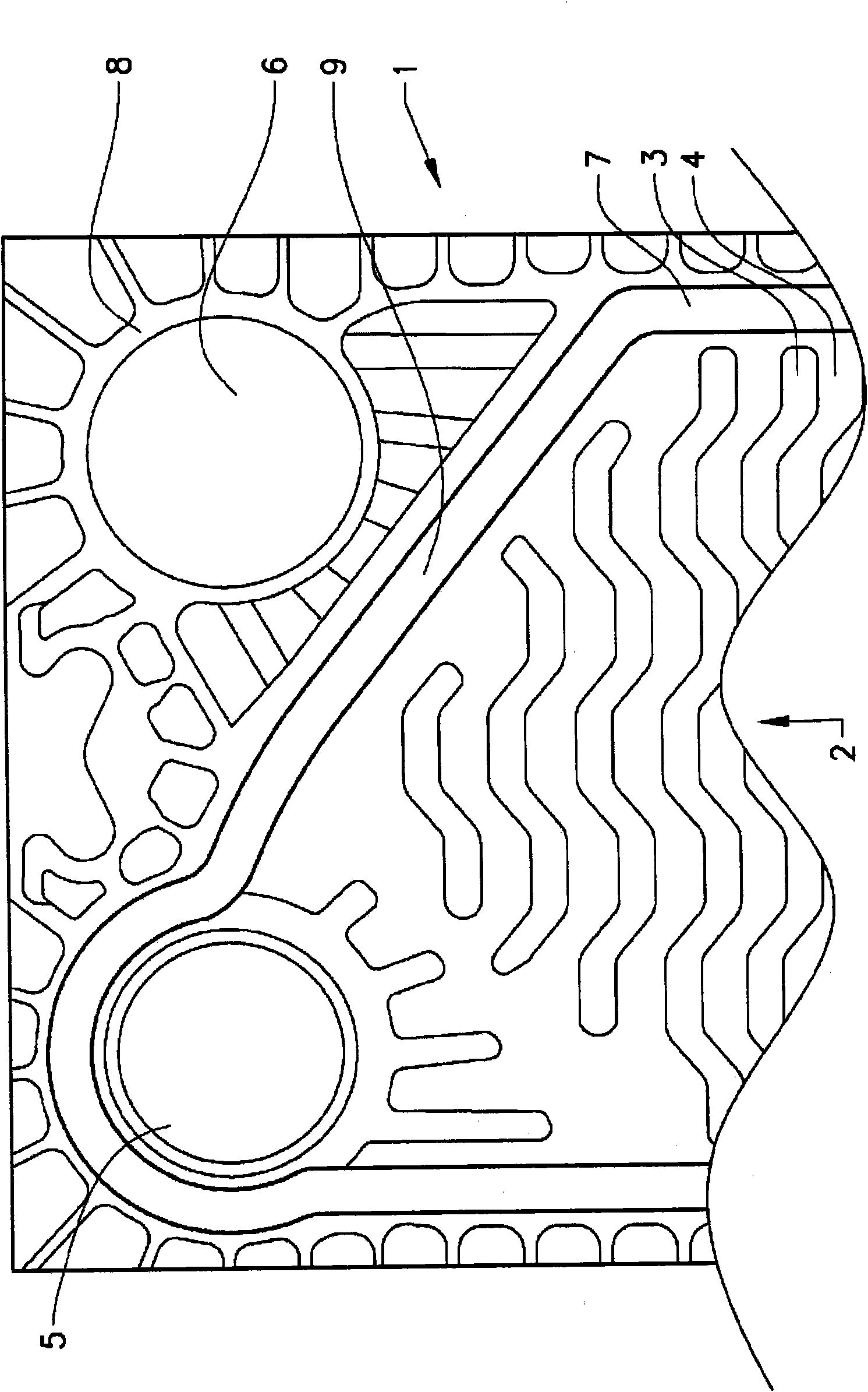
[0037] Figure 1 shows a part of a prior art contactless cassette for a heat exchanger disclosed in WO2006 / 080874. The heat exchanger cassette 1 includes two orifices constituting an inlet 5 and an outlet 6 and a heat transfer surface 2 having a ridge 3 and a valley 4. The plate also includes sealing gaskets suitable for sealing the fluid passages in the heat exchanger. The gasket 7 seals the contact-free product flow channel, and the annular gasket 8 seals the port for cooling / heating fluid. The liner 7 includes diagonal liner segments 9 which define the boundaries of the product channel at the distribution area of ​​the inlet and outlet. The diagonal gasket section 9 is located in the diagonal gasket groove. Since the diagonal gasket groove is angled with respect to the lengt...


PUM


Abstract

A diagonal gasket support (22) in a heat exchanger cassette adapted for a heat exchanger having a contact-free flow channel (28), where the cassette (11, 29) comprises two plates (12) of the same type, where each plate is provided with a corrugated pattern having a plurality of ridges (19) and valleys (20), characterized in that the diagonal gasket support (22) comprises a plurality of indentations (23) and protrusions (24) positioned adjacent each other along a diagonal gasket groove (21). The advantage of such a diagonal gasket support is that a contact-free support at the diagonal gasket is obtained.

Description

Technical field [0001] The present invention relates to a gasket support in a plate heat exchanger with contact-free distribution channels. The present invention also relates to a heat exchanger including a plurality of heat exchanger cassettes with gasket brackets. Background technique [0002] Food manufacturing is typically characterized by the need to process and handle high viscosity products, for example, concentrates for carbonated beverages, juices, soups, dairy products, and other fluid consistency products. Due to natural reasons, the hygienic wishes and expectations in this regard are very high to meet the requirements of various regulatory agencies. High-viscosity fluids containing particles or fibers are also used in other areas of the industry, such as in different processing industries. [0003] Plate heat exchangers are used in this industry for many different purposes. One problem with using plate heat exchangers such as those used in the food industry is that s...

Claims


Application Information

Patent Timeline
IPC IPC(8): F28F3/10
CPCF28F3/10F28D9/00
Inventor J·克兰茨M·斯文森
Owner ALFA LAVAL CORP AB
Why Eureka
Try Eureka