Method and device for detection and identification of gases

A gas and molecular technology, applied in the field of gas identification, which can solve the problems of inability to immediately detect the chemical mixture to be measured, long measurement time, and complex technology.

Active Publication Date: 2010-12-15
AIRSENSE ANALYTICS
View PDF7 Cites 17 Cited by
  • Summary
  • Abstract
  • Description
  • Claims
  • Application Information

AI Technical Summary

Benefits of technology

This patented technology relates to methods for accurately measuring small amounts (1 nm) of materials called volatile organic solvents (VOC). These VOCS have unique characteristics such as being able to absorb light energy when excited upward towards specific frequencies while emitting electromagnetic radiation. By comparing measurements made during excitation with those obtained beforehand, it becomes easier to determine if there were any harmful particles within them. Additionally, the use of certain types of voltages allows for more accurate detection even down to extremely thin layers of matter like coal. Overall, this technology provides technical benefits over existing techniques including but limited applications in various fields such as environmental monitoring, chemical analysis, biological research, medical diagnosis, etc., making it suitable for wide range of uses across industries.

Problems solved by technology

This patented technical problem addressed in this patents relates to improving the accuracy and efficiency of separations performed during analysis of charged particles without sacrificing resolution capabilities when analyzing complex mixtures containing multiple types of atoms.

Method used


Image

  • Method and device for detection and identification of gases
  • Method and device for detection and identification of gases
  • Method and device for detection and identification of gases

Examples


Embodiment Construction

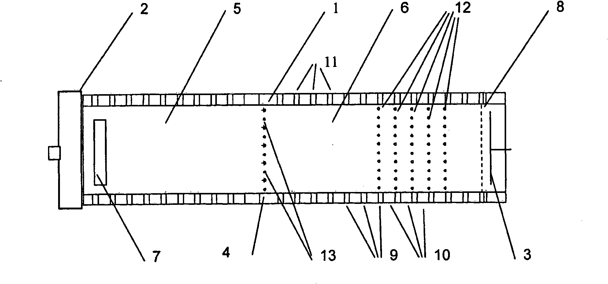
[0076] Such as figure 1 As shown, the new device for identifying gases in the embodiment includes a drift tube 1, one end of which is connected to an intake system 2, and the other end is connected to a detector 3, and its structure is a flat conductive disk.

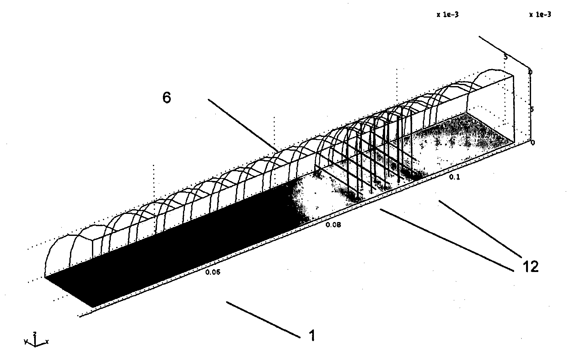
[0077] In the drift tube 1 there is an electromotive switching network 4 , by means of which the interior space in the drift tube 1 is divided into a reaction zone 5 and a drift zone 6 . The reaction zone 5 is connected to the intake system 2 , and the drift zone 6 is connected to the detector 3 . In addition, an ion source 7 is arranged near the intake system 2 in the reaction zone 5, a shielding grid 8 is arranged in the drift zone 6, and the shielding grid 8 is located in front of the detector 3, wherein the ion source 7 is covered with a radioactive Ni63 foil, shield grid 8 is used to provide capacitive decoupling. The switching grid 4 is called Bradbury-Nielsen grid, which is composed of two conductive metal comb...


PUM


Abstract

The aim of the invention, is to develop a method of the type in question, for identification of gases and a corresponding device, which has a simple construction permitting an immediate and concurrent detection of the chemical compounds under examination and hence for identification of the material-specific mobility and at the same time the change in said mobility as a function of electrical field strength. Said aim is achieved, wherein each ionised molecule has a drift speed through the resultant electrical field, which is partly increased or reduced, the resulting electrical field being a DC field, with a superimposed asymmetrical alternating field. Said method and corresponding devices for detection and identification of gases are used for recognition and detection of chemical compounds, in particular of explosive and/or toxic materials or material compounds for detection in extremely low concentrations.

Description


Claims


Application Information

Patent Timeline
Owner AIRSENSE ANALYTICS
Why Eureka
Try Eureka