Suspension type upsetting material gathering die structure

A hanging and upsetting technology, which is applied in the direction of manufacturing tools, forging/pressing/hammer devices, forging/pressing/hammering machinery, etc., can solve the problems of low production efficiency and failure to meet the use requirements, and improve the upsetting efficiency , Improve the effect of upsetting quality

Active Publication Date: 2013-03-13
AKITA GEAR CO LTD MACHINERY EQUIP BRANCH
View PDF0 Cites 0 Cited by
  • Summary
  • Abstract
  • Description
  • Claims
  • Application Information

AI Technical Summary

Problems solved by technology

[0002] In the process of metal processing, it is often necessary to upset the long metal blank to shorten its length and increase its diameter, and to upset the metal blank. The ratio of the length to diameter of the upset part is usually less than 2.5. Metal blanks whose diameter ratio is greater than 2.5 times are upset, usually by multi-pass extrusion or free forging, and the production efficiency is extremely low; if the metal blank is directly placed between the upper and lower flat anvils or upsetting flat plates for flat anvil Upsetting, the metal blank is easy to bend its long metal blank and form folds, which cannot meet the requirements of use

Method used


Image

  • Suspension type upsetting material gathering die structure
  • Suspension type upsetting material gathering die structure
  • Suspension type upsetting material gathering die structure

Examples


Embodiment Construction

[0021] Below in conjunction with accompanying drawing and embodiment the present invention will be further described:

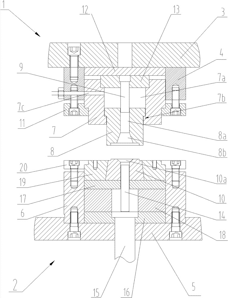
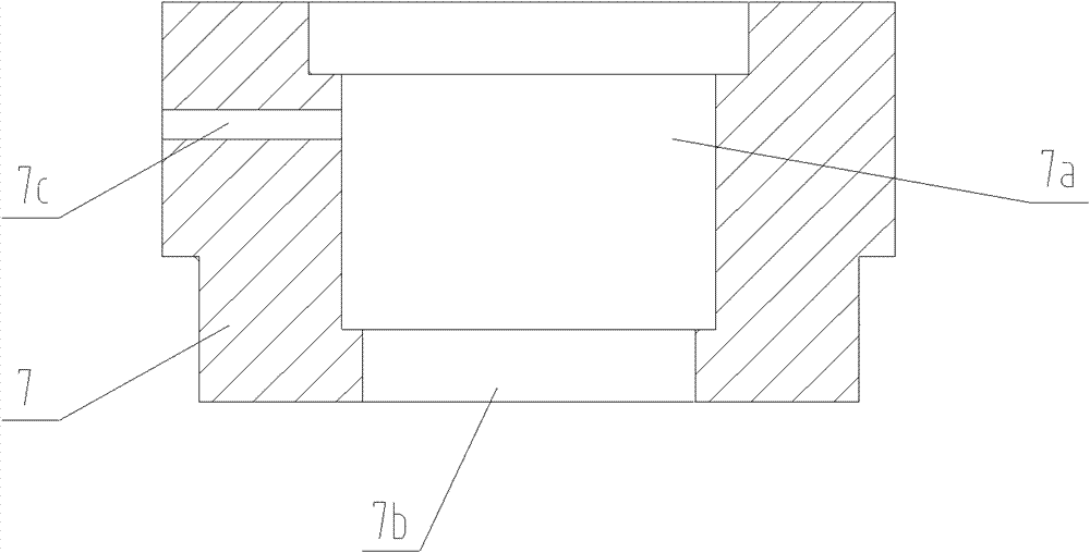
[0022] Such as Figure 1 to Figure 6 Shown, a kind of suspended upsetting aggregate mold structure, comprises upper mold 1 and lower mold 2, and upper mold 1 comprises an upper formwork 3 and the cylindrical upper mold base 4 that is fixed on the lower surface of upper formwork 3, upper formwork 3 and the upper mold base 4 are connected and fixed by screws, the lower surface of the upper template 3 is fixed with an upper backing plate 12, and the lower surface of the upper backing plate 12 is fixed with an upper punch fixing plate 13, and a cylindrical upper punch 9 is vertical It is fixed on the lower side of the upper punch fixing plate 13 and is located in the inner chamber 7a of the upper die casing, and the upper backing plate 12 and the upper punch fixing plate 13 are all located in the upper die base 4 . The upper mold base 4 is provided with an upper...


PUM


Abstract

The invention relates to a suspension type upsetting material gathering die structure which comprises an upper template, an upper die base, a lower template and a lower die base, and has the key points as follows: an upper die sleeve is fixed in the upper die base, the upper die sleeve is provided with a cylindrical inner cavity, the lower cavity opening of the inner cavity is provided with a spacing seam allowance, and the diameter of the spacing seam allowance is smaller than that of the cylindrical inner cavity; an upper die core is movably sleeved in the cylindrical inner cavity of the upper die sleeve, one end of the upper die core is provided with a spacing flange part which is positioned in the inner cavity of the upper die sleeve and is in slide fit with the inner cavity of the upper die sleeve, and the other end of the upper die core penetrates out from the spacing seam allowance of the upper die sleeve and is in slide fit with the spacing seam allowance; the upper die core is axially provided with a through hole and an upper cavity which are communicated with each other, the upper cavity is positioned at the lower end of the through hole, and an upper top dash is vertically fixed in the inner cavity of the upper die sleeve and is inserted into the through hole in the upper die core in a sliding mode; and the lower die base is internally fixed with a lower female die corresponding to the upper die core, and the lower female die is provided with a lower cavity corresponding to the upper cavity. The invention improves the upsetting quality of strip metal blanks and the upsetting efficiency.

Description

technical field [0001] The invention relates to a metal upsetting tool, in particular to a suspension type upsetting aggregate mold structure. Background technique [0002] In the process of metal processing, it is often necessary to upset the elongated metal blank to shorten its length and increase its diameter, and to upset the metal blank. The ratio of the length to diameter of the upsetting part is usually less than 2.5. Metal blanks whose diameter ratio is greater than 2.5 times are upset, usually by multi-pass extrusion or free forging, and the production efficiency is extremely low; if the metal blanks are directly placed between the upper and lower flat anvils or upsetting plates for flat anvils Upsetting, metal blanks are prone to bending and folding of the long metal blanks, which cannot meet the requirements of use. Contents of the invention [0003] The technical problem to be solved by the present invention is: the purpose of the present invention is to provi...

Claims


Application Information

Patent Timeline
Patent Type & Authority Patents(China)
IPC IPC(8): B21J13/02
Inventor 蔡利刘太钟
Owner AKITA GEAR CO LTD MACHINERY EQUIP BRANCH
Why Eureka
Try Eureka