A die closing upsetter and a working method
A working method and upsetting machine technology, applied in upsetting presses, swaging presses, forging/pressing/hammering machines, etc., can solve problems such as troublesome debugging, difficulty in high-speed upsetting, high coordination requirements, etc., and achieve improvement The effect of upsetting forging efficiency, improving work efficiency and convenient adjustment
- Summary
- Abstract
- Description
- Claims
- Application Information
AI Technical Summary
Problems solved by technology
Method used
Image
Examples
Embodiment 1
[0066] In this embodiment, the specific structure and working method of the die-clamping upsetting machine will be described by using the one-touch-one-punch die-clamping upsetting machine.
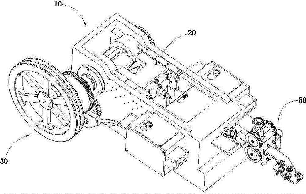
[0067] Such as figure 1 , figure 2 and image 3 As shown, the die-clamping upset forging machine includes a body 10, a punch assembly 20 installed on the body 10, a punch assembly driving mechanism 30 for driving the punch assembly 20, a feeding mechanism 50 arranged on the body 10, and a mold clamping assembly 90.
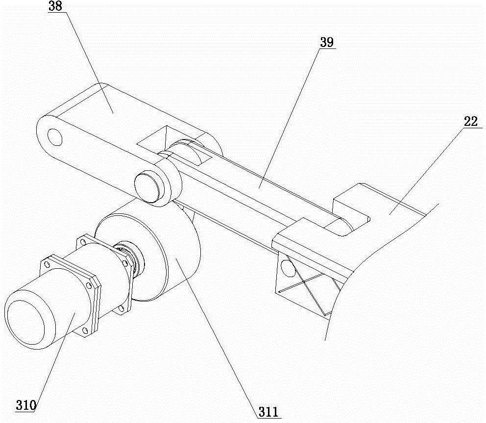
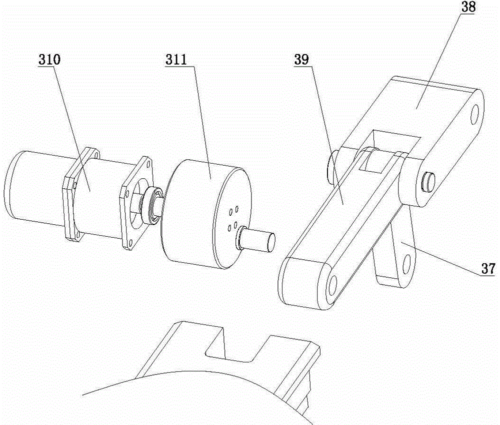
[0068] Such as figure 2 and image 3 As shown, the body 10 includes a frame 11, a base body 12 and a cover plate 13; the frame 11 includes a frame body 111 and a frame seat 112, and the frame seat 112 includes a frame body 1122 and an end plate 1123 , the base body 1122 has an accommodating cavity 1121 , the two ends of the accommodating cavity 1121 have openings 11211 , and the end plates 1123 are fixed on the base body 1122 at the openings. In this embodiment, the t...
Embodiment 2
[0099] In this embodiment, the specific structure and working method of the die-clamping upsetting machine will be described by using the one-touch-one-punch die-clamping upsetting machine.
[0100] Such as figure 1 , figure 2 and image 3 As shown, the die-clamping upset forging machine includes a body 10, a punch assembly 20 installed on the body 10, a punch assembly driving mechanism 30 for driving the punch assembly 20, a feeding mechanism 50 arranged on the body 10, and a mold clamping assembly 90.
[0101] Such as figure 2 and image 3 As shown, the body 10 includes a frame 11, a base body 12 and a cover plate 13; the frame 11 includes a frame body 111 and a frame seat 112, and the frame seat 112 includes a frame body 1122 and an end plate 1123 , the base body 1122 has an accommodating cavity 1121 , the two ends of the accommodating cavity 1121 have openings 11211 , and the end plates 1123 are fixed on the base body 1122 at the openings. In this embodiment, the t...
Embodiment 3
[0153] In this embodiment, the specific structure and working method of the die-clamping upsetting machine will be described by using the one-touch-one-punch die-clamping upsetting machine.
[0154] Such asfigure 1 , figure 2 and image 3 As shown, the die-clamping upset forging machine includes a body 10, a punch assembly 20 installed on the body 10, a punch assembly driving mechanism 30 for driving the punch assembly 20, a feeding mechanism 50 arranged on the body 10, and a mold clamping assembly 90.
[0155] Such as figure 2 and image 3 As shown, the body 10 includes a frame 11, a base body 12 and a cover plate 13; the frame 11 includes a frame body 111 and a frame seat 112, and the frame seat 112 includes a frame body 1122 and an end plate 1123 , the base body 1122 has an accommodating cavity 1121 , the two ends of the accommodating cavity 1121 have openings 11211 , and the end plates 1123 are fixed on the base body 1122 at the openings. In this embodiment, the two...
PUM
 Abstract
Description
Claims
Application Information
 - R&D
- Intellectual Property
- Life Sciences
- Materials
- Tech Scout
- Unparalleled Data Quality
- Higher Quality Content
- 60% Fewer Hallucinations
Browse by: Latest US Patents, China's latest patents, Technical Efficacy Thesaurus, Application Domain, Technology Topic, Popular Technical Reports.
© 2025 PatSnap. All rights reserved.Legal|Privacy policy|Modern Slavery Act Transparency Statement|Sitemap|About US| Contact US: help@patsnap.com


