Automatic power control circuit for controlling bias current of laser diode

An automatic power control, laser diode technology, applied in circuits, lasers, laser parts, etc., can solve problems such as cumbersome comparison procedures, increased circuit complexity of the comparator 14, and increased circuit power consumption.

Inactive Publication Date: 2012-05-23
TM TECHNOLOGY INC
View PDF0 Cites 0 Cited by
  • Summary
  • Abstract
  • Description
  • Claims
  • Application Information

AI Technical Summary

Problems solved by technology

[0011] Although the existing automatic power control circuit 100 can negatively feedback control the bias current (Ibias) of the laser diode 18 to reach a rated current value, however, the sample-and-hold signal (SH) representing the luminous intensity of the laser diode 18 must be compared with multiple sets of reference voltages at the same time. Only by comparing R1, R2, R3, and R4 can we know whether the bias current of the laser diode is equal to a rated current value. In this way, not only the comparison procedure is too cumbersome, but also the circuit complexity of the comparator 14 is increased, and therefore It is very unfavorable to increase the power consumption of the circuit

Method used


Image

  • Automatic power control circuit for controlling bias current of laser diode
  • Automatic power control circuit for controlling bias current of laser diode
  • Automatic power control circuit for controlling bias current of laser diode

Examples


Embodiment Construction

[0059] The present invention will be described in detail below in conjunction with the accompanying drawings and specific embodiments, but not as a limitation of the present invention.

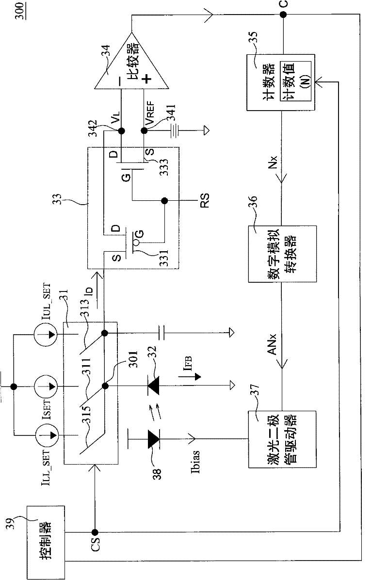
[0060] First, please refer to figure 2 , is a circuit structure diagram of a preferred embodiment of the automatic power control loop for controlling the bias current of the laser diode according to the present invention. As shown in the figure, the automatic power control circuit 300 is applied to the adjustment of the luminous intensity of the optical signal in an optical communication system, which includes a switch selector 31, a photodiode 32, a converter 33, a comparator 34, and a counter 35 . A laser diode driver 37 , a laser diode 38 and a controller 39 .

[0061] Wherein, the laser diode 38 receives a bias current (Ibias) to drive to emit light as a light source of the optical signal. The photodiode 32 senses the luminous intensity of the laser diode 38 to generate a negative feedb...


PUM


Abstract

The invention relates to an automatic power control circuit for controlling the bias current of a laser diode, which comprises a photodiode, wherein the photodiode is used for sensing the luminous intensity of the laser diode so as to generate a negative feedback current; one of rated currents is selected according to a control signal; the current difference between the selected rated current andthe negative feedback current is converted into a load voltage; a comparison signal is generated by comprising a reference voltage with the load voltage; a counting valve adds the value, decreases the value or maintains the present value according to the comparison signal and the control signal; and a laser diode drive is used for receiving the adjusted counting value so as to generate a pair of bias currents to drive the laser diode to emit light. Therefore, the bias current of the laser diode is adjusted by negative feedback to be in an admissible range to enable a light source emitted by the laser diode to be maintained at a certain luminous intensity.

Description

technical field [0001] The present invention relates to an automatic power control circuit for controlling the bias current of a laser diode. Negative feedback adjusts the bias current of the laser diode to an allowable range, so as to keep the light source emitted by the laser diode at a fixed luminous intensity . Background technique [0002] A common optical communication system transmits an optical signal through an optical fiber to conduct data communication, and generally uses a laser diode as a light source for the optical signal. In the past optical communication systems, an automatic power control loop (Automatic Power Control; APC) was used to monitor the luminous intensity of the laser diode, and the bias current of the laser diode was controlled by feedback to reach a rated current value, so that the light source emitted by the laser diode could be Maintain a constant luminous intensity. [0003] like figure 1 Shown is the circuit structure diagram of the exis...

Claims


Application Information

Patent Timeline
Patent Type & Authority Patents(China)
IPC IPC(8): H01S5/0683
Inventor 王智扬王启萍
Owner TM TECHNOLOGY INC
Why Eureka
Try Eureka