Sound reproducing device

A reproduction device and audio technology, applied in digital recording/reproduction, speech analysis, instruments, etc., can solve problems such as inability to achieve high-quality sound processing, flaws in the processing capacity of audio reproduction devices, and increased processing capacity.

Inactive Publication Date: 2012-06-06
PANASONIC CORP
View PDF1 Cites 0 Cited by
  • Summary
  • Abstract
  • Description
  • Claims
  • Application Information

AI Technical Summary

Problems solved by technology

[0017] However, when performing these processes, since the properties of the stream to be decoded, the required audio processing functions, and the processing of additional audio data, etc. are included, when the above processes are implemented on the same device, The processing capability required varies depending on the attributes of the stream or playback conditions
First, when the sampling frequency for reproducing PCM is increased due to the properties of the bit stream or the reproduction request for high-quality sound processing, the processing amount of the processing of the external sound may be increased accordingly, and the processing of the entire audio reproduction device may be overwhelmed. Amount of flaws
[0018] Moreover, in order to avoid this, it is necessary to increase the sampling frequency of the reproduced PCM, but in this case, the sound quality of the decoded PCM may be deteriorated or the high-quality sound processing required from the outside may not be realized.

Method used


Image

  • Sound reproducing device
  • Sound reproducing device
  • Sound reproducing device

Examples


Embodiment approach 1

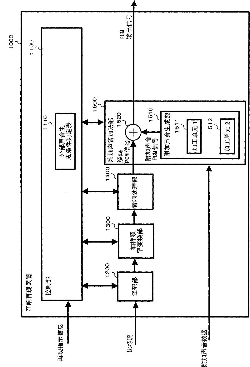
[0122] figure 1 The structure of the sound reproduction apparatus of Embodiment 1 is shown. This sound reproduction device 1000 includes a control unit 1100 , a decoding unit 1200 , a sampling frequency conversion unit 1300 , a sound processing unit 1400 , and an additional sound addition unit 1500 .

[0123] The decoding unit 1200 decodes an externally input audio bit stream to generate and output a decoded PCM signal. When decoding the audio bit stream, the decoding unit 1200 outputs decoder type information, sampling frequency information, and channel configuration information to the control unit 1100 as decoding information.

[0124]The control unit 1100 receives the playback instruction information from the outside and the decoding information from the decoding unit 1200, and judges whether the decoded PCM signal has sampling frequency conversion or various audio processing, and performs the sampling frequency conversion unit 1300, audio processing. The processing unit...

Embodiment approach 2

[0152] Figure 5 The structure of the sound reproduction apparatus of Embodiment 2 is shown. This audio reproduction device 2000 includes a control unit 1100 , a sampling frequency conversion unit 1300 , an audio processing unit 1400 , an additional audio addition unit 1500 , and an additional audio data buffer 1600 built in.

[0153] Internally installed additional audio data buffer 1600 is a buffer for storing additional audio data installed inside audio reproduction device 2000, and stores additional audio data corresponding to each sampling frequency necessary for reproduction.

[0154] The control unit 1100 refers to the external sound generation condition determination table 1110 based on the decoded information and the playback instruction information, and determines which of the externally input additional sound data or the internally installed additional sound data is used as the additional sound generated by the additional sound adding unit 1500. Section 1510 provides...

Embodiment approach 3

[0184] Figure 10 The structure of the sound reproduction apparatus of Embodiment 3 is shown. This audio reproduction device 3000 includes a control unit 1100 , a decoding unit 1200 , a sampling frequency conversion unit 1300 , an audio processing unit 1400 , an additional audio addition unit 1500 , and a PCM output buffer 1700 .

[0185] The control unit 1100 receives the playback instruction information from the outside and the decoding information from the decoding unit 1200, and judges whether the decoded PCM signal has sampling frequency conversion or various audio processing, and performs the sampling frequency conversion unit 1300, audio processing. The processing unit 1400 and the additional sound adding unit 1500 instruct processing. In the present embodiment, the externally acquired playback instruction information includes, in addition to processing instructions for each audio processing function, designation of an underflow condition of the PCM output buffer remai...


PUM


Abstract

A sound reproducing device comprises a decoding unit (1200) for decoding an audio signal bit stream inputted from outside and generating a decoded PCM signal, a control unit (1100) for specifying a reproduction condition according to reproduction instruction information acquired from outside and decoding information acquired from the decoding unit (1200) and issuing a reproduction instruction, and an additive audio adding unit (1500) for processing additive audio data inputted from outside, adding the processed additive audio data to the decoded PCM signal, and outputting the sum signal as a PCM output signal. The additive audio adding unit (1500) has an additive audio crating section (1510) for processing the additive audio data so that the additive audio data can be added to the decodedPCM signal and outputting the processed additive audio data as an additive audio PCM signal, and an adder (1520) for mixing the additive audio PCM signal and the decoded PCM signal. The additive audio generating section (1510) is composed of a plurality of processing means (1511, 1512) corresponding to the trade-off between the magnitude of the load of the processing computational complexity and the sound characteristic of the processing result. The control unit (1100) specifies one of the processing means (1511, 1512) according to the reproduction instruction information and decoding information. The additive audio generating section (1510) processes the additive audio data by using the specified processing means.

Description

technical field [0001] The present invention relates to a digital signal processing technology, in particular to decoding an externally input sound signal bit stream to generate a decoded PCM signal, and then processing additional sound data input from outside to add to the above-mentioned decoded PCM signal Calculate and output to an external audio reproduction device. Background technique [0002] In recent years, due to the popularization and technical progress of various digital media reproduction devices such as digital televisions and optical disc devices, various functions have been mounted on media reproduction devices involving digital processing. As one of the functions in such a background, for example, a function of mixing and outputting an external sound such as a guide sound or a warning sound with a digital TV broadcast sound or an optical disc reproduction sound may be provided. Furthermore, in the case of performing such external sound mixing processing on ...

Claims


Application Information

Patent Timeline
Patent Type & Authority Patents(China)
IPC IPC(8): G10L19/00G11B20/10
CPCG11B20/10527G11B2020/10805G11B2020/10546G11B2020/10759G11B27/034
Inventor 藤田刚史后藤宏之秋吉伸一山田周平松本正治
Owner PANASONIC CORP
Why Eureka
Try Eureka