Synchronous time updating method and device

A technology for synchronizing time and updating method, applied in the directions of synchronization devices, network data management, electrical components, etc., can solve the problem of long network synchronization time, etc., to achieve the effect of improving efficiency and eliminating clock delay errors

Active Publication Date: 2010-12-29
HONOR DEVICE CO LTD
View PDF0 Cites 8 Cited by
  • Summary
  • Abstract
  • Description
  • Claims
  • Application Information

AI Technical Summary

Problems solved by technology

[0010] Embodiments of the present invention provide a method and device for updating synchronization time, which can effectively solve the problem of too long time for network synchronization in existing low-power routing networks in the prior art

Method used


Image

  • Synchronous time updating method and device
  • Synchronous time updating method and device
  • Synchronous time updating method and device

Examples


Embodiment 1

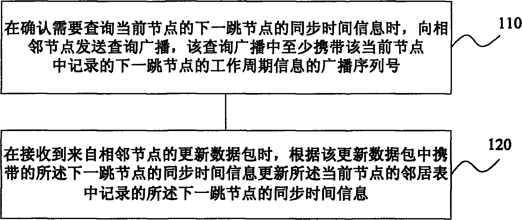
[0040] An embodiment of the present invention provides a synchronization time update method in a low-power routing sensor network, such as figure 2 As shown, the method includes the following steps:

[0041] Step 110, when it is confirmed that the synchronization time information of the next-hop node of the current node needs to be queried, a query broadcast is sent to the adjacent node, and the query broadcast carries at least the working cycle broadcast sequence number of the next-hop node recorded in the current node .

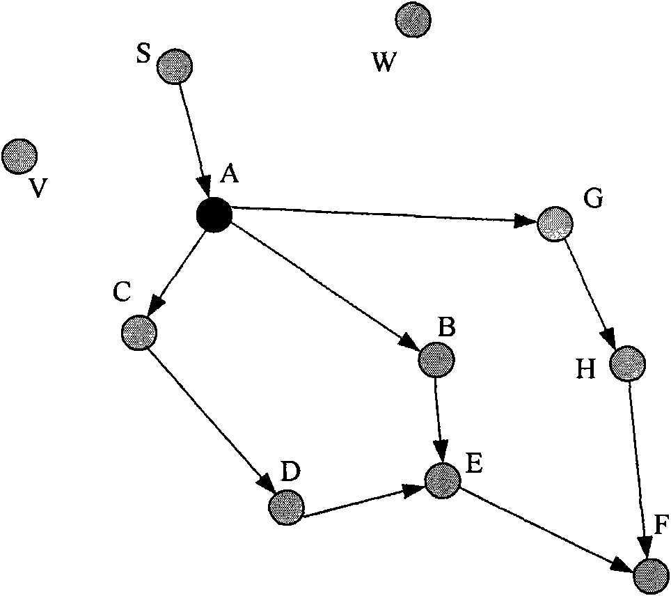
[0042] in such as figure 1 In the shown low-power routing sensor network, the neighbor tables of each node record the synchronization time information of their respective adjacent nodes, maintaining a relative synchronization state. If a data packet needs to be sent from source node S to node F, the specific path can be selected from S->A->B->E->F. For node A, a data packet from the last hop node S will be received.

[0043] When the data packet arrive...

Embodiment 2

[0056] Embodiments of the present invention further provide a method for updating synchronization time in a low-power routing sensor network. The basic process of this embodiment is the same as that of Embodiment 1, except that the method of feeding back the duty cycle information of the queried node from the surrounding adjacent nodes is different. Such as Figure 4 As shown, the method of the present embodiment includes the following steps:

[0057] Step 210, receiving a query broadcast from node A, where the query broadcast carries synchronization time information of the queried node.

[0058] When node A confirms that it needs to query the synchronization time information of node B, node B is the queried node, and node A sends a query broadcast to adjacent nodes, and the query broadcast at least carries node B's work cycle broadcast sequence in node A's neighbor table No.

[0059] Neighboring nodes of node B will receive the query broadcast from node A.

[0060] Step 2...

Embodiment 3

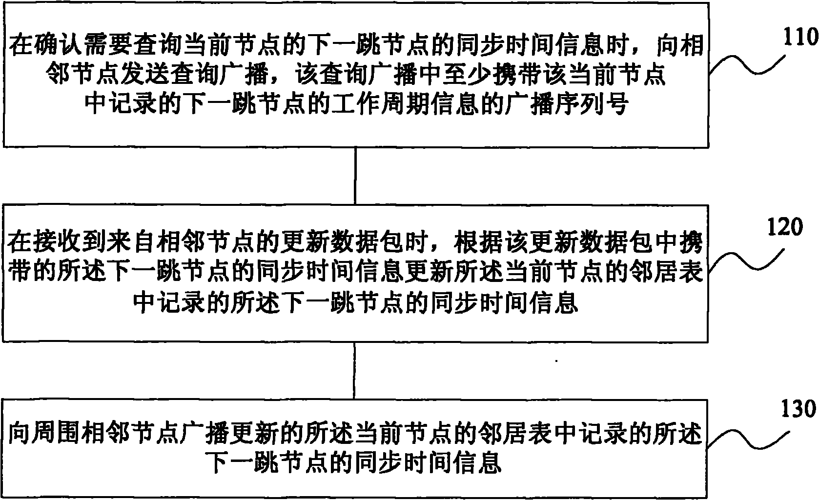
[0073] This embodiment also provides a method for updating synchronization time in a low-power routing sensor network. The method of this embodiment is basically the same as that of Embodiment 2, except that when the node sends a query broadcast packet, it not only includes the time of the queried target node The work cycle information also contains the latest work cycle information of itself. In this way, the node can also update the relevant synchronization information in the neighbor table of the adjacent nodes around itself while completing the query of the latest work cycle of the target node.

[0074] Such as Image 6 As shown, the method of the present embodiment includes:

[0075] Step 310, receiving a query broadcast from node A, the query broadcast carrying the synchronization time information of the node being queried and the synchronization time information of node A itself.

[0076] When node A confirms that it needs to query the synchronization time information...


PUM


Abstract

The embedment of the invention provides a synchronous time updating method and a synchronous time updating device. The method comprises: when determining it is necessary to query the synchronous time information of a next-hop node of a current node, sending query broadcast to the neighboring nodes of the current node, wherein the broadcast at least carries the working period broadcast serial number, which is recorded in the current node, of the next-hop node; and receiving update data packets from the neighboring nodes of the current node, and updating the synchronous time information, which is recorded in a neighbor list of the current node, of the next-hop node according to the synchronous time information, which is carried by the update data packets, of the next-hop node of the currentnode.

Description

technical field [0001] The invention relates to wireless network communication technology, in particular to a synchronization time update method and device in a low-power routing sensor network. Background technique [0002] Wireless sensor network is a constantly developing network communication technology, which can be applied in industrial control, home monitoring, data communication and other fields. A wireless sensor network is data-centric and consists of many wireless sensor nodes with the same or different functions. Wireless sensor nodes can include terminal nodes, collection nodes, and management nodes. Terminal nodes collect data from the surrounding environment and transmit data directly or indirectly to collection nodes through wireless links; collection nodes are mainly responsible for collecting data collected by all terminal nodes in a specific area. , after data fusion, it is sent to the upper management node. The wireless sensor network not only has the c...

Claims


Application Information

Patent Timeline
Patent Type & Authority Applications(China)
IPC IPC(8): H04W4/06H04W8/00H04W56/00H04W84/18
Inventor 徐勇
Owner HONOR DEVICE CO LTD
Why Eureka
Try Eureka