Multi-shell tube-shell-and-tube -type condenser with heat recoverer

A recoverer and multi-shell side technology, which is applied in the direction of evaporator/condenser, heat exchanger shell, refrigerator, etc., can solve the problem of increasing the overall size of the unit, low fluid velocity on the shell side, and low heat transfer coefficient of the heat exchanger. Advanced problems, to achieve the effect of improving the condensation heat transfer efficiency and reducing the heat transfer temperature difference loss

Inactive Publication Date: 2011-01-05
ZHONGYUAN ENGINEERING COLLEGE
View PDF6 Cites 6 Cited by
  • Summary
  • Abstract
  • Description
  • Claims
  • Application Information

AI Technical Summary

Problems solved by technology

[0002] The air conditioning unit with heat recovery can produce domestic hot water while cooling, saving energy and reducing the amount of cooling water, which is energy-saving and environmentally friendly. However, at present, it is mostly realized by connecting condensers in series or in parallel, which makes the control and pipeline connection complicated. , increasing the overall size of the unit and increasing the cost of the unit
Most of the condensers currently used have a single-shell shell side. When the heat transfer of the heat exchanger is large, the diameter of the shell is large and the flow cross-section of the single shell side is large, resulting in a low velocity of the fluid on the shell side, resulting in a large heat exchanger. The overall heat transfer coefficient of the heater is not high, and the heat transfer efficiency is low

Method used


Image

  • Multi-shell tube-shell-and-tube -type condenser with heat recoverer
  • Multi-shell tube-shell-and-tube -type condenser with heat recoverer
  • Multi-shell tube-shell-and-tube -type condenser with heat recoverer

Examples


Embodiment 1

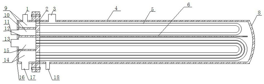
[0019] Such as figure 1 As shown, the multi-shell-side shell-and-tube condenser with heat recovery device of the present invention includes tube box 16, tube plate I2 and plate II7, shell 4, end cover 8 and so on. The tube box 16 is connected to the outside of the tube sheet 2 and a partition I12 is arranged inside to divide the tube box into a heat recovery zone 9 and a condensation zone 14. In the heat recovery zone 9, a partition II10 is provided to separate the heat recovery zone, The tube side above the heat recovery area is provided with a pipe interface I1, the tube side below the heat recovery area is provided with a pipe interface II11, and a partition III15 is provided in the condensation area 14 to divide the condensation area, and the tubes above the condensation area Set the pipe interface III13 on the tube side, and set the tube interface IV17 on the tube side below the condensation area. The end cover 8 is connected to the outside of the tube sheet II7, and a p...

Embodiment 2

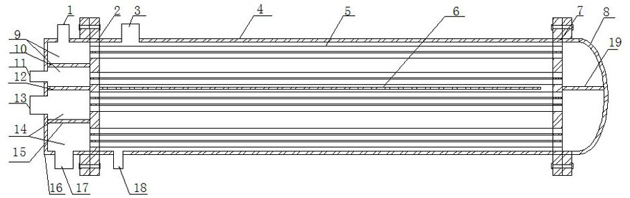
[0022] Such as figure 2 As shown, the heat exchange tube is a U-shaped heat exchange tube, and the rest of the structure is the same as that of Embodiment 1.


PUM


Abstract

The invention relates to a multi-shell shell-and-tube-shell- type condenser with a heat recoverer. The condenser comprises a channel (16), tube plates (2 and 7), a shell (4) and an end cover (8). The tube plates are respectively arranged at both ends of the shell, the channel (16) is connected with the outer side of the tube plates (2) and internally provided with a separator to divide the channel into a heat recovery area (9) and a condensing area (14), the shell is provided with the end cover (8) at the other end and internally provided with a heat exchange pipe (5) which penetrates through the tube plates (2 and 7) and are communicated the channel and the end cover, and the shell is internally provided with a longitudinal deflectorflow-guiding plate (6) to divide the interior of the shell into the overheat steam heat recovery area and the condensing area. The heat exchanger of the invention can recover overheat steam through the separation of the overheat steam heat recovery area and the condensing area.

Description

technical field [0001] The invention relates to heat exchange equipment, especially a multi-shell-side shell-and-tube condenser combining heat recovery and condensation. Background technique [0002] The air conditioning unit with heat recovery can produce domestic hot water while cooling, saving energy and reducing the amount of cooling water, which is energy-saving and environmentally friendly. However, at present, it is mostly realized by connecting condensers in series or in parallel, which makes the control and pipeline connection complicated. , increasing the overall size of the unit and increasing the cost of the unit. Most of the condensers currently used have a single-shell shell side. When the heat transfer of the heat exchanger is large, the diameter of the shell is large and the flow cross-section of the single shell side is large, resulting in a low velocity of the fluid on the shell side, resulting in a large heat exchanger. The overall heat transfer coefficie...

Claims


Application Information

Patent Timeline
Patent Type & Authority Applications(China)
IPC IPC(8): F25B39/04F28F9/02
Inventor 周光辉陈圣洁
Owner ZHONGYUAN ENGINEERING COLLEGE
Why Eureka
Try Eureka