Split type multi-stage heat pipe system

A split type, heat pipe technology, applied in the field of heat exchange, can solve the problems of large heat exchange temperature difference loss and low total heat exchange efficiency, and achieve the effects of reducing heat exchange temperature difference loss, great flexibility, and improving heat exchange efficiency

Inactive Publication Date: 2013-01-09
BEIJING FULLLINK OREITH TECH CO LTD
View PDF5 Cites 4 Cited by
  • Summary
  • Abstract
  • Description
  • Claims
  • Application Information

AI Technical Summary

Problems solved by technology

[0009] A new type of heat pipe heat exchange device technology provided by the present invention—a split multi-stage heat pipe system is to solve the problems of large heat exchange temperature difference loss and low total heat exchange efficiency when the current heat pipe is working

Method used


Image

  • Split type multi-stage heat pipe system
  • Split type multi-stage heat pipe system

Examples


Embodiment Construction

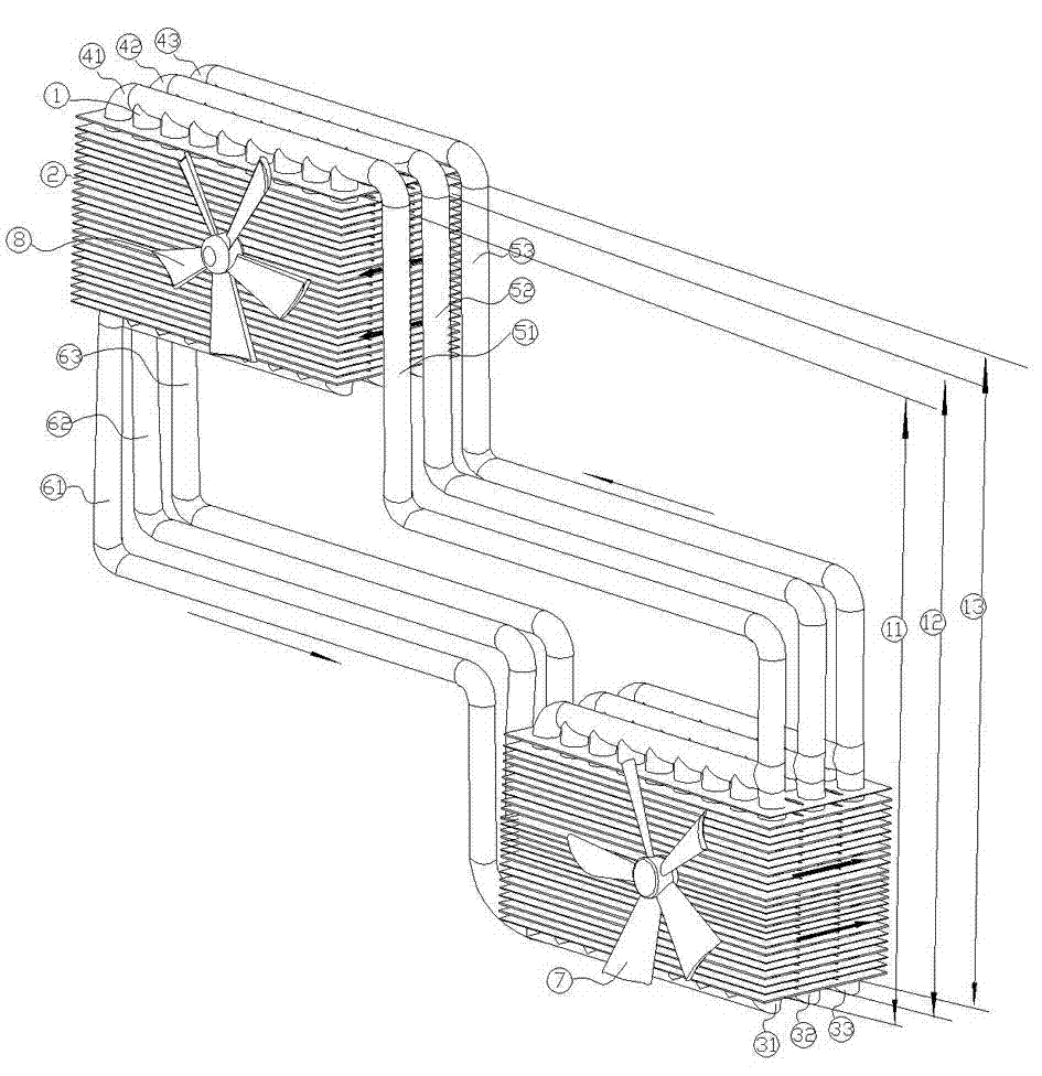
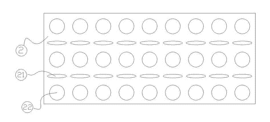
[0024] The simple structural diagram of this embodiment is as follows: figure 1 As shown; the main structure of the system device involved in the implementation of this embodiment includes a heat pipe unit (1), a primary heat pipe group (11), a secondary heat pipe group (12), a tertiary heat pipe group (13), and cooling fins (2 ), thermal insulation seam (21), perforation (22), evaporator of the primary heat pipe group (31), evaporator of the secondary heat pipe group (32), evaporator of the third heat pipe group (33), primary heat pipe The condenser (41) of the second heat pipe group, the condenser (42) of the second heat pipe group, the condenser (43) of the third heat pipe group, the steam channel (51) of the first heat pipe group, the steam channel (52) of the second heat pipe group ), the steam channel (53) of the third-stage heat pipe group, the liquid channel (61) of the first-stage heat pipe group, the liquid channel (62) of the second-stage heat pipe group, the liquid...


PUM


Abstract

The invention discloses a split type multi-stage heat pipe system which mainly comprises a first-stage heat pipe group, a second-stage heat pipe group, a third-stage heat pipe group, heat pipe units and a connection pipeline, and an N-stage heat pipe group can be formed as required. The whole split type multi-stage heat pipe system is composed of condensers, evaporators, steam channels and liquid channels. The evaporators and the condensers of the first-stage heat pipe group, the second-stage heat pipe group and the third-stage heat pipe group are respectively a group of independent circulation loop formed by the heat pipe units with the same quantity in parallel connection mode. The evaporators of the system are arranged on the lower portions of the condensers, the steam channels enable the top ends of the first-stage heat pipe group, the second-stage heat pipe group and the third-stage heat pipe group to be respectively connected with the top ends of the condensers, and the liquid channels enable the bottom ends of the first-stage heat pipe group, the second-stage heat pipe group and the third-stage heat pipe group to be respectively connected with the bottom ends of the condensers. The evaporators and the condensers of the whole system are separated. The split type multi-stage heat pipe system can achieve remote heat transfer so that the system is large in process design flexibility and good conditions are created for device scaling-up, heat energy comprehensive utilization and heat energy utilization system optimization.

Description

technical field [0001] The present invention relates to the technical field of heat exchange, in particular to a novel heat pipe heat exchange system, in particular to a split-type multi-stage heat pipe system in which multiple sets of independent heat pipe devices are placed side by side. Background technique [0002] The heat pipe uses evaporative refrigeration to make the temperature difference between the two ends of the heat pipe very large, so that the heat can be conducted quickly. Because of its superior heat transfer performance and technical characteristics, it is widely used in the field of energy saving. At present, heat pipes are commonly used in equipment cooling, waste heat recovery, and fresh air systems. The total driving temperature difference of the heat pipe heat exchanger is the temperature difference between the evaporation section and the condensation section. The constant temperature characteristic of the refrigerant inside the single-stage heat pipe ...

Claims


Application Information

Patent Timeline
Patent Type & Authority Applications(China)
IPC IPC(8): F28D15/02
Inventor 祝长宇丁式平
Owner BEIJING FULLLINK OREITH TECH CO LTD
Why Eureka
Try Eureka