Supercharge Your Innovation With Domain-Expert AI Agents!

Double-fibre passive bus type optical network structure

A network structure, bus-type technology, applied in the direction of bus-type electromagnetic network, electromagnetic network arrangement, etc., can solve problems such as signal superposition

Inactive Publication Date: 2013-02-27
CHINA AVIATION OPTICAL-ELECTRICAL TECH CO LTD
View PDF4 Cites 0 Cited by
  • Summary
  • Abstract
  • Description
  • Claims
  • Application Information

AI Technical Summary

Problems solved by technology

[0003] The purpose of the present invention is to provide a dual-fiber passive bus optical network structure to solve the problem of signal superposition in the prior art

Method used


Image

  • Double-fibre passive bus type optical network structure
  • Double-fibre passive bus type optical network structure
  • Double-fibre passive bus type optical network structure

Examples


Embodiment Construction

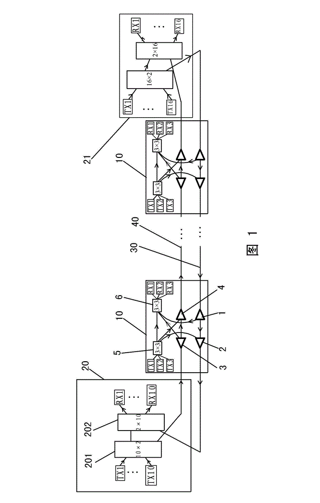
[0011] Such as figure 1 As shown, Embodiment 1 of the present invention is composed of two first and second main optical fibers 30, 40 extending in parallel and opposite to the direction of transmitting optical signals, and a plurality of nodes connected to the two main optical fibers. There are two types of connection structures with the main optical fiber, one is four along-line node connection structures 10 distributed one by one along the extension direction of the main optical fiber, of course, 1 to 3 or More than 4, the other is the connection structure 20, 21 of the termination node connected to the two ends of the two main optical fibers. The arrows in the figure represent the direction of optical signal transmission.

[0012] Each of the node connection structures 10 along the line is composed of three optical transmitting modules TX1-TX3 and three optical receiving modules RX1-RX3 connected through a plurality of optical couplers. The optical couplers in each node ...


PUM


Abstract

The invention discloses a double-fibre passive bus type optical network structure comprising two main optical fibres, an along-line node connection structure and an end node connection structure, wherein the along-line node connection structure is connected to the two main optical fibres, and the end node connection structure is connected to the two ends of the two main optical fibres; each along-line node connection structure is formed by connecting more than one light emission module with a light receiver module by a plurality of optical couplers; each along-line node connection structure comprises the following optical couplers: first to fourth 1*2 optical couplers, a P*3 optical coupler and a 3*P optical coupler; and the end node connection structure is composed of an N*2 star-type optical coupler, a 2*N star-type optical coupler, a corresponding light emission module and a corresponding light receiver module. Any one node in the bus type optical network can receive optical signals emitted by all nodes including self for once.

Description

technical field [0001] The invention relates to the technical field of optical fiber communication. Background technique [0002] The existing passive bus-type optical network structure is mainly composed of two main optical fibers and nodes connected to the two main optical cables. Each node contains more than one optical transmitting module TX and optical receiving module RX. The optical signal sent by a node can be received by all nodes including itself, and any two nodes on the bus can realize the intercommunication of optical signals. In order to add more nodes in the bus-type optical network, you can add Add a star optical splitter coupler at one or both ends. Such as image 3 As shown, in an existing optical network structure, the left end is connected to an N×N star-shaped optical branch coupler, and the right end is connected to an M×M star-shaped optical branch coupler. When an optical signal is input from any TX port, All RXs can be received. However, this stru...

Claims


Application Information

Patent Timeline
Patent Type & Authority Patents(China)
IPC IPC(8): H04B10/278
Inventor 林琳
Owner CHINA AVIATION OPTICAL-ELECTRICAL TECH CO LTD
Features
  • R&D
  • Intellectual Property
  • Life Sciences
  • Materials
  • Tech Scout
  • Unparalleled Data Quality
  • Higher Quality Content
  • 60% Fewer Hallucinations
Learn More