Eureka AIR delivers breakthrough ideas for toughest innovation challenges, trusted by R&D personnel around the world.

Tableware washer

A tableware washing machine and technology for cleaning objects, which is applied in the direction of tableware washing machine/rinsing machine, tableware washing machine/rinsing and rinsing machine parts, cleaning equipment, etc., and can solve the problem of wall transmittance decrease and other problems

Active Publication Date: 2012-10-31
PANASONIC CORP
View PDF1 Cites 0 Cited by
  • Summary
  • Abstract
  • Description
  • Claims
  • Application Information

AI Technical Summary

Problems solved by technology

However, as the number of times the dishwasher is used increases, the dirt contained in the washing water adheres to the wall surface.
As a result, the transmittance of the wall surface decreases

Method used

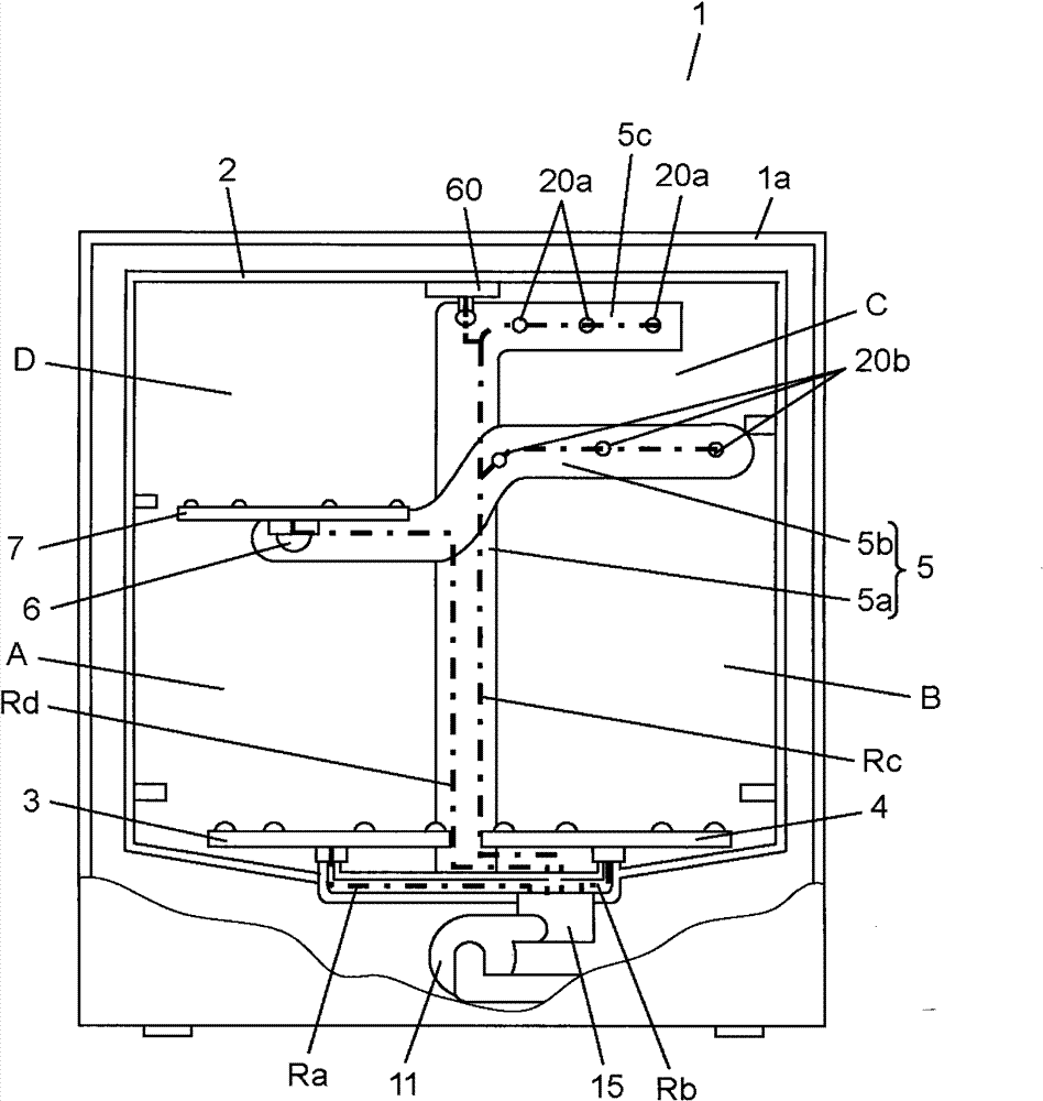

Image

  • Tableware washer
  • Tableware washer
  • Tableware washer

Examples


Embodiment Construction

[0026] Next, a dishwasher according to an embodiment of the present invention will be described with reference to the drawings. In the following description, the liquid used for washing and rinsing of objects to be washed such as tableware is referred to as washing water.

[0027] (1) The structure of the dish washing machine

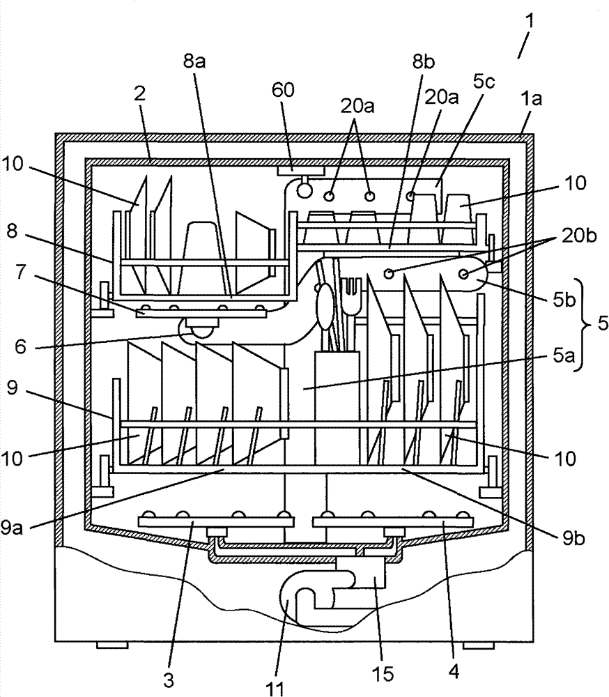
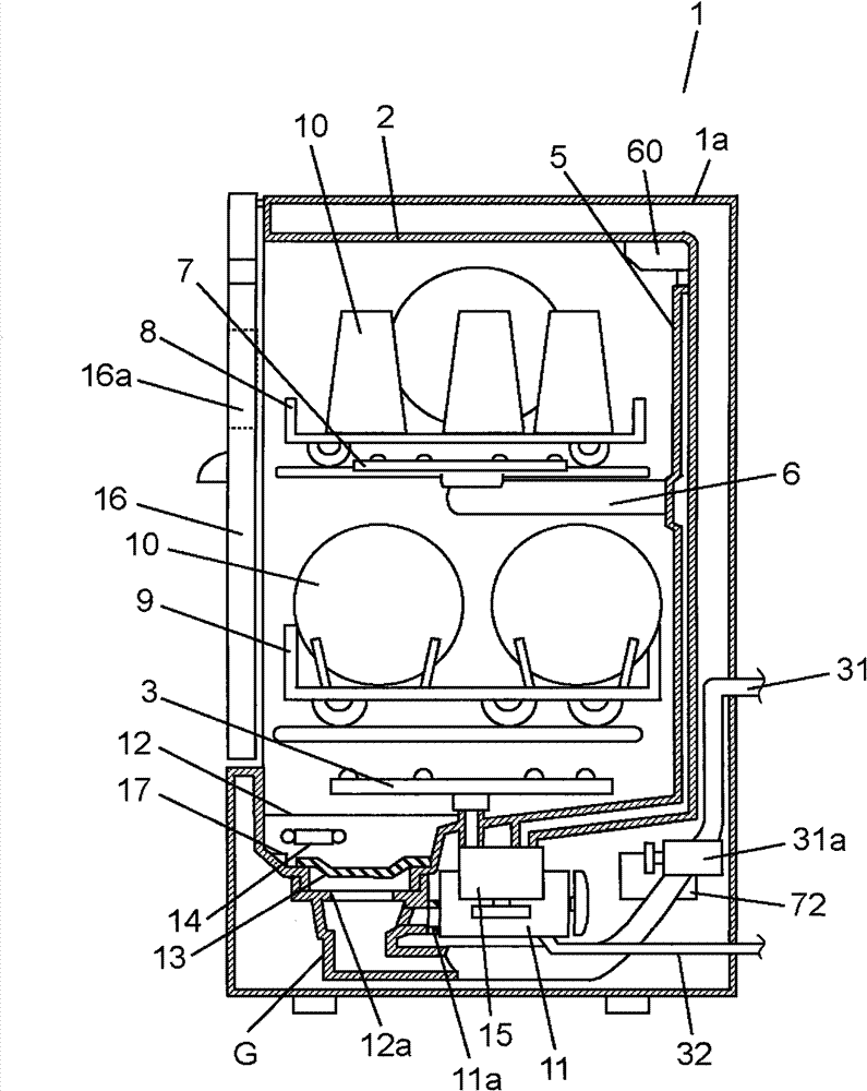
[0028] figure 1 and figure 2 It is a front view and a side view which show the structure of the dishwasher concerning embodiment of this invention. exist figure 1 In the front view of , a part of the front of the dishwasher 1 is cut away and illustrated. In addition, in figure 2 The interior of the dishwasher 1 is shown in perspective in the side view of . In addition, front and rear, left and right, and up and down in this embodiment mean front and back, left and right, and up and down when the dishwasher 1 is viewed from the front.

[0029] Such as figure 1 and figure 2 As shown, the dishwasher 1 includes a housing 1a. On the front surfac...


PUM


Abstract

The invention relates to a tableware washer having a storage part for storing washings, and a washings jetting mechanism, the jetting mechanism jets the washings stored in the storage part to objects to be washed in a washing tank to clean the objects. The washer comprises a turbidity detection part, which is located at a position higher than a water level of residual water of the washings storedin the storage part, and used for detecting the turbidity of the washings. The washer further comprises a control part for adjusting a detected value of turbidity to be a reference value before a period of cleaning via action of the washings jetting mechanism, and then, setting a cleaning condition according to the turbidity of the washings. Thereby, dreggy degree of the objects to be cleaned canbe accurately detected for long time.

Description

technical field [0001] The invention relates to a tableware washing machine for washing tableware. Background technique [0002] There is a dishwasher equipped with an optical sensor for detecting turbidity of wash water used for washing dishes. The optical sensor detects the transmittance of the wash water as the turbidity of the wash water. As such a dishwasher, for example, the dishwasher described in JP-A-6-22896 (Patent Document 1) will be described. [0003] In the dishwasher of Patent Document 1, at least a part of the wall surface of a water suction pipe provided between a water reservoir provided at the bottom of the sink and the water suction side of the nozzle pump is formed of, for example, a translucent material. In addition, a light-emitting element and a light-receiving element for detecting changes in the transmittance of the liquid inside the water suction pipe are provided. Thus, a photosensor is formed. The steps of washing, rinsing, draining, and dryi...

Claims


Application Information

Patent Timeline
Patent Type & Authority Patents(China)
IPC IPC(8): A47L15/42
CPCA47L15/22A47L15/4297
Inventor 莊司彰永井克幸铃木将大
Owner PANASONIC CORP
Why Eureka
Eureka Blog
Learn More