Position detecting system and position detecting method

A detection system and detection value technology, applied in diagnostic recording/measurement, medical science, surgery, etc., can solve problems such as inseparability, poor position detection accuracy, and different Fourier transform phases

Inactive Publication Date: 2015-04-01
OLYMPUS CORP
View PDF7 Cites 0 Cited by
  • Summary
  • Abstract
  • Description
  • Claims
  • Application Information

AI Technical Summary

Problems solved by technology

However, in this method, there is a problem that when the phase of the driving magnetic field changes due to time-dependent changes in the driving magnetic field generating unit, temperature changes, and interference with the LC resonant circuit, etc., the Fourier transform will be distorted. The phase of the start timing will be different, so that the separation cannot be performed correctly, and the position detection accuracy will deteriorate

Method used


Image

  • Position detecting system and position detecting method
  • Position detecting system and position detecting method
  • Position detecting system and position detecting method

Examples


Embodiment approach 1

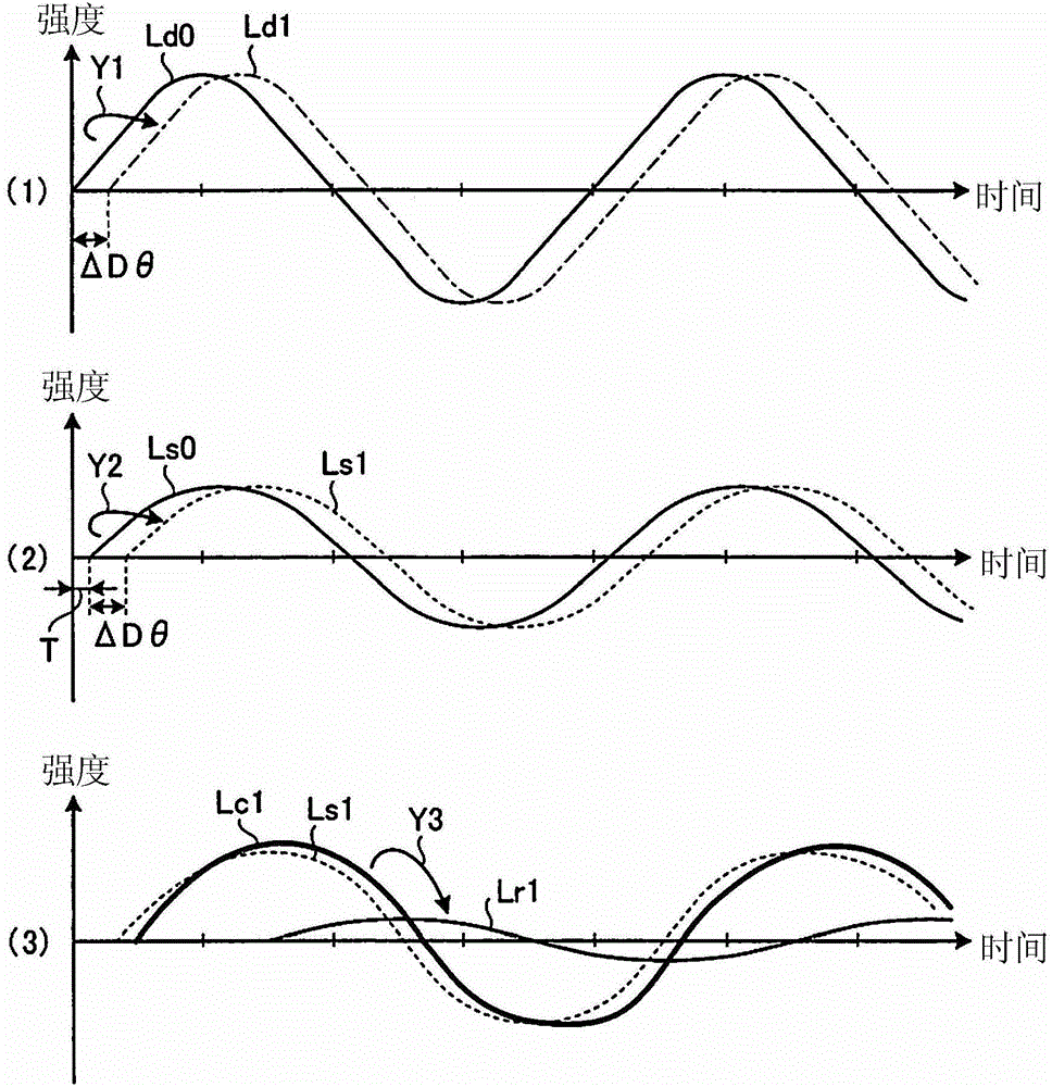
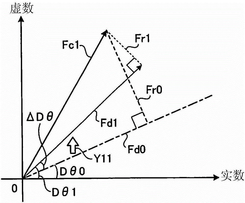
[0058] Next, the configuration and operation of the position detection system 1 according to Embodiment 1 of the present invention will be described in detail using the drawings. In addition, the present embodiment realizes a position detection system and a position detection method that can detect the position of the object with high accuracy by obtaining the driving magnetic field component that is currently occurring, and separating the resonant magnetic field component based on the driving magnetic field component. Influenced by changes in the driving magnetic field over time or the like.

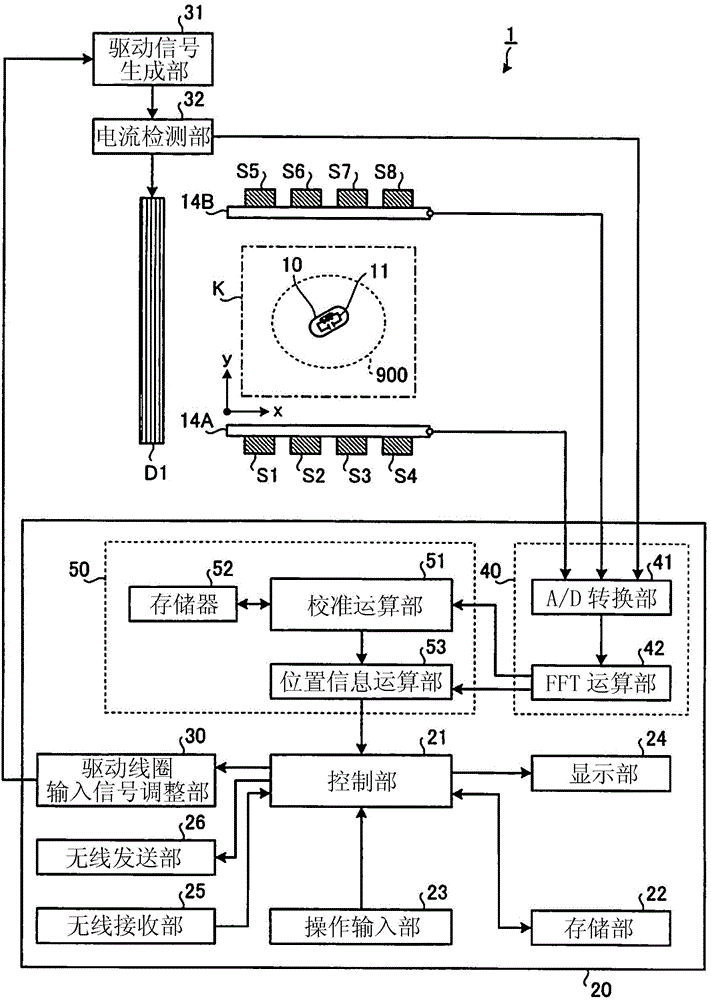
[0059] figure 1 It is a schematic diagram showing the schematic configuration of the position detection system 1 according to the first embodiment. Such as figure 1 As shown, the position detection system 1 according to Embodiment 1 includes: a detection space K for accommodating the subject 900 into which the capsule endoscope 10 is introduced; and an external device 20 for detecti...

Embodiment approach 2

[0174] Next, Embodiment 2 will be described. Figure 18 It is a schematic diagram showing the schematic configuration of the position detection system 201 according to the second embodiment. Such as Figure 18 As shown, the position detection system 201 according to the second embodiment includes a plurality of magnetic field generating coils D1 and D2 that form a substantially uniform driving magnetic field in the detection space K, and includes driving coils D1 and D2 respectively corresponding to the magnetic field generating coils D1 and D2. Signal generators 31a, 31b and current detectors 32a, 32b.

[0175] Furthermore, the position detection system 201 is equipped with an external device 220 instead of figure 1 The external device 20 is shown. The external device 220 has a control unit 221 instead of figure 1 The control unit 21 shown has a drive coil input signal adjustment unit 230 instead figure 1 The driving coil input signal adjustment part 30 shown has a co...


PUM


Abstract

A position detecting system 1 of the present invention includes a capsule endoscope 10 disposed in a detection space K to generate a resonance magnetic field in response to a driving magnetic field generated in the detection space K; a magnetic field generating coil D1 that generates the driving magnetic field in the detection space; detecting coils S1 to S8 that that detect a synthetic magnetic field of the driving magnetic field and the resonance magnetic field generated by the capsule endoscope 10 in response to the driving magnetic field; a current detecting unit 32 that detects a driving current flowing through the magnetic field generating coil D1 in synchronization with magnetic field detection by the detecting coils S1 to S8; and a position information calculating unit 50 that calculates a position and a direction of the capsule endoscope 10 based on a detection value of the synthetic magnetic field that is detected by the detecting coils S1 to S8 and a detection value of the driving current that is detected by the current detecting unit 32.

Description

technical field [0001] The present invention relates to a position detection system and a position detection method, and in particular to a position detection system and a position detection method for detecting the position of a capsule-type intra-subject introduction device introduced into a subject using a magnetic field. Background technique [0002] In recent years, a capsule-type sample equipped with an imaging element (hereinafter referred to as a capsule endoscope) has been developed (for example, refer to Patent Document 1 shown below). The capsule endoscope is introduced into the subject through the oral cavity, for example, takes images of the subject, and wirelessly transmits the obtained images (hereinafter referred to as in-subject images) to an external device placed outside the subject. The operator can diagnose the symptoms of the subject and the like by visually confirming the internal image of the subject received from the external device. [0003] In a m...

Claims


Application Information

Patent Timeline
Patent Type & Authority Patents(China)
IPC IPC(8): A61B1/00
CPCA61B1/00158A61B1/041A61B5/062
Inventor 饭田隆广
Owner OLYMPUS CORP
Why Eureka
Try Eureka