Sound source separation system, sound source separation method, and acoustic signal acquisition device

a separation system and sound source technology, applied in the field of sound source separation system, a sound source separation method and an acoustic signal acquisition device, can solve the problems of difficult to hear, unnatural force on users to use a close-talking type microphone,

Inactive Publication Date: 2009-12-31
WASEDA UNIV
View PDF11 Cites 35 Cited by
  • Summary
  • Abstract
  • Description
  • Claims
  • Application Information

AI Technical Summary

Problems solved by technology

On the other hand, there are lots of applications, such as interaction with a robot, operation of an in-vehicle device like a car navigation system through a speech, and creation of conference minutes, where enforcing a user to use a close-talking type micr...

Method used


Image

  • Sound source separation system, sound source separation method, and acoustic signal acquisition device
  • Sound source separation system, sound source separation method, and acoustic signal acquisition device
  • Sound source separation system, sound source separation method, and acoustic signal acquisition device

Examples


first embodiment

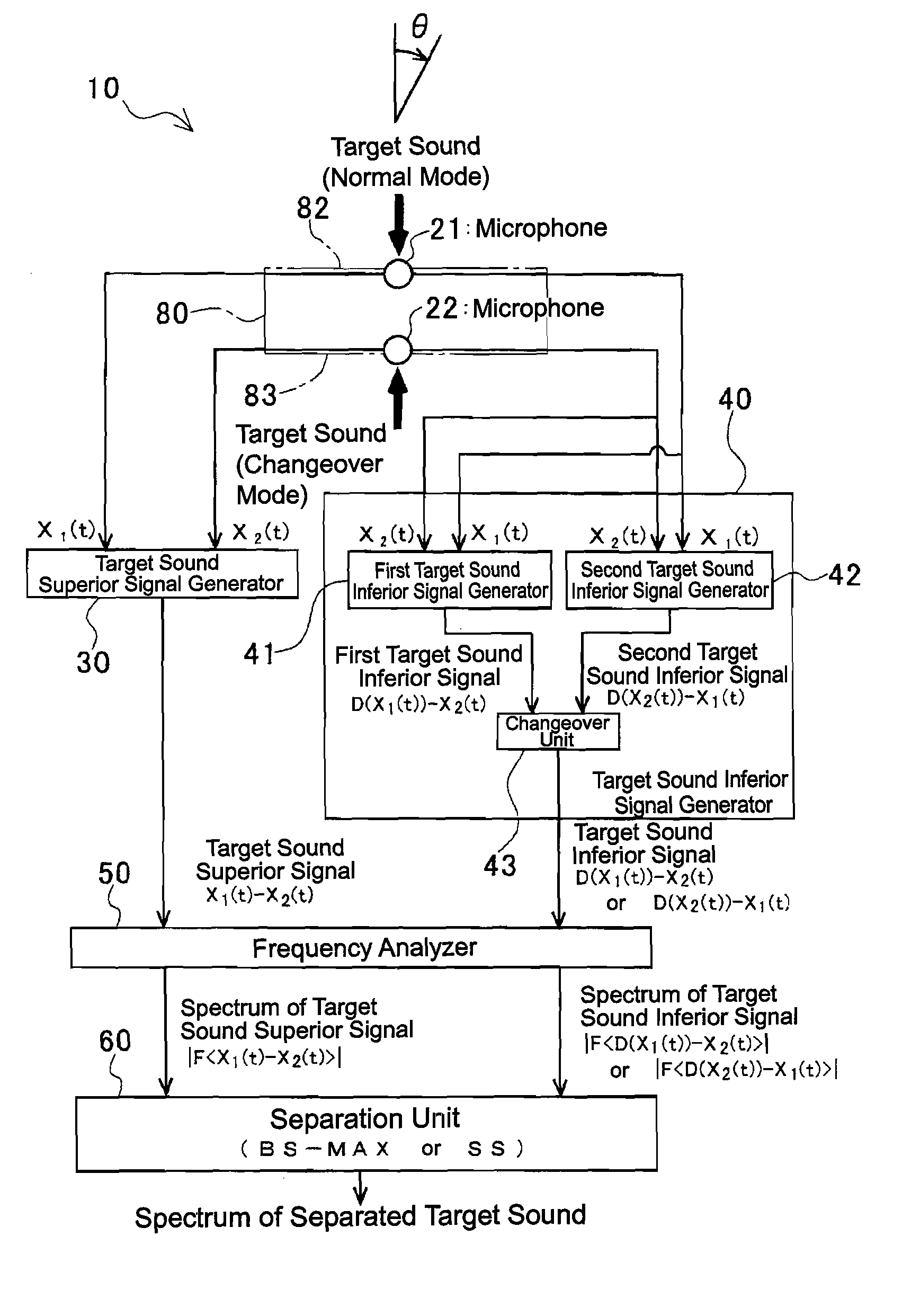
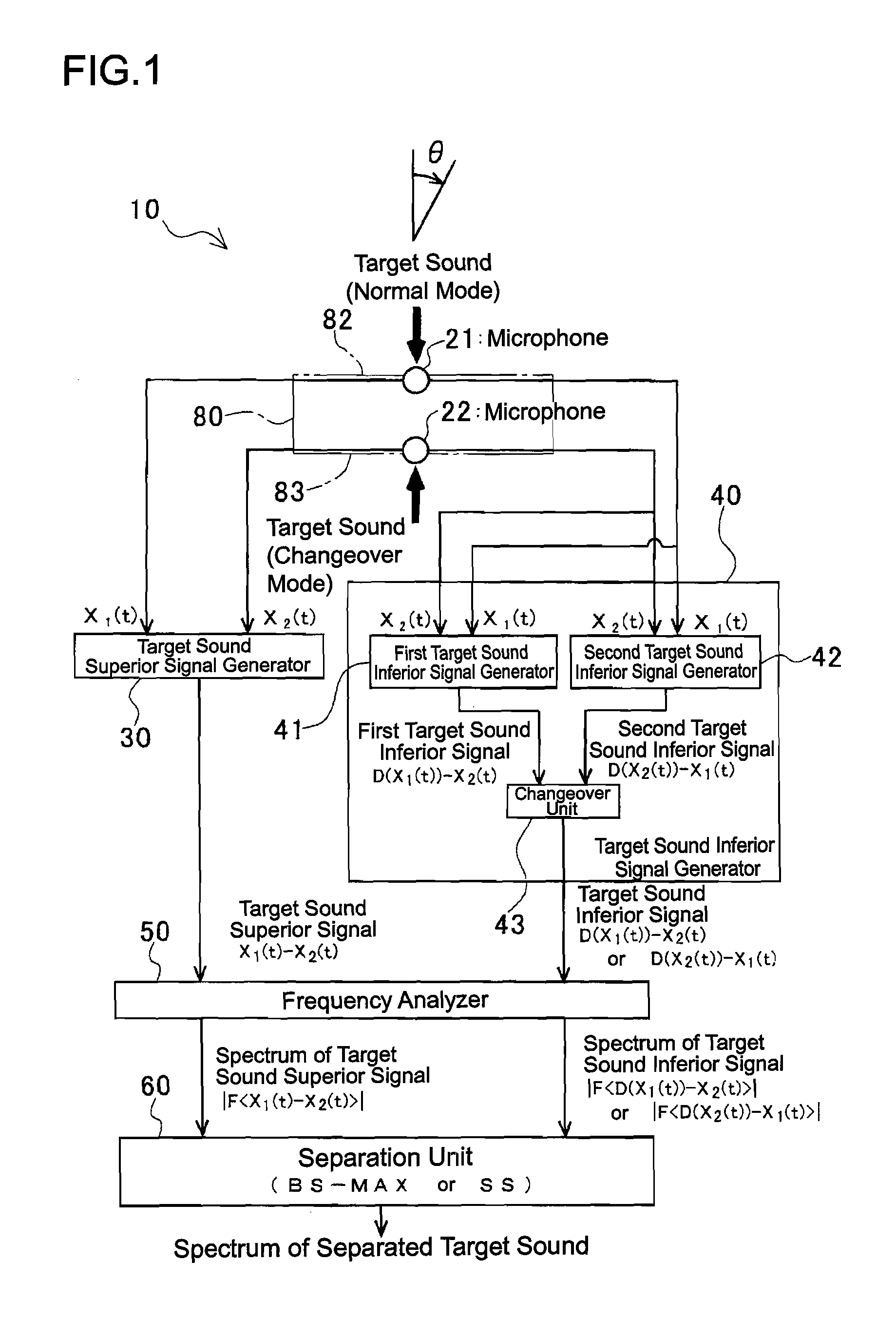
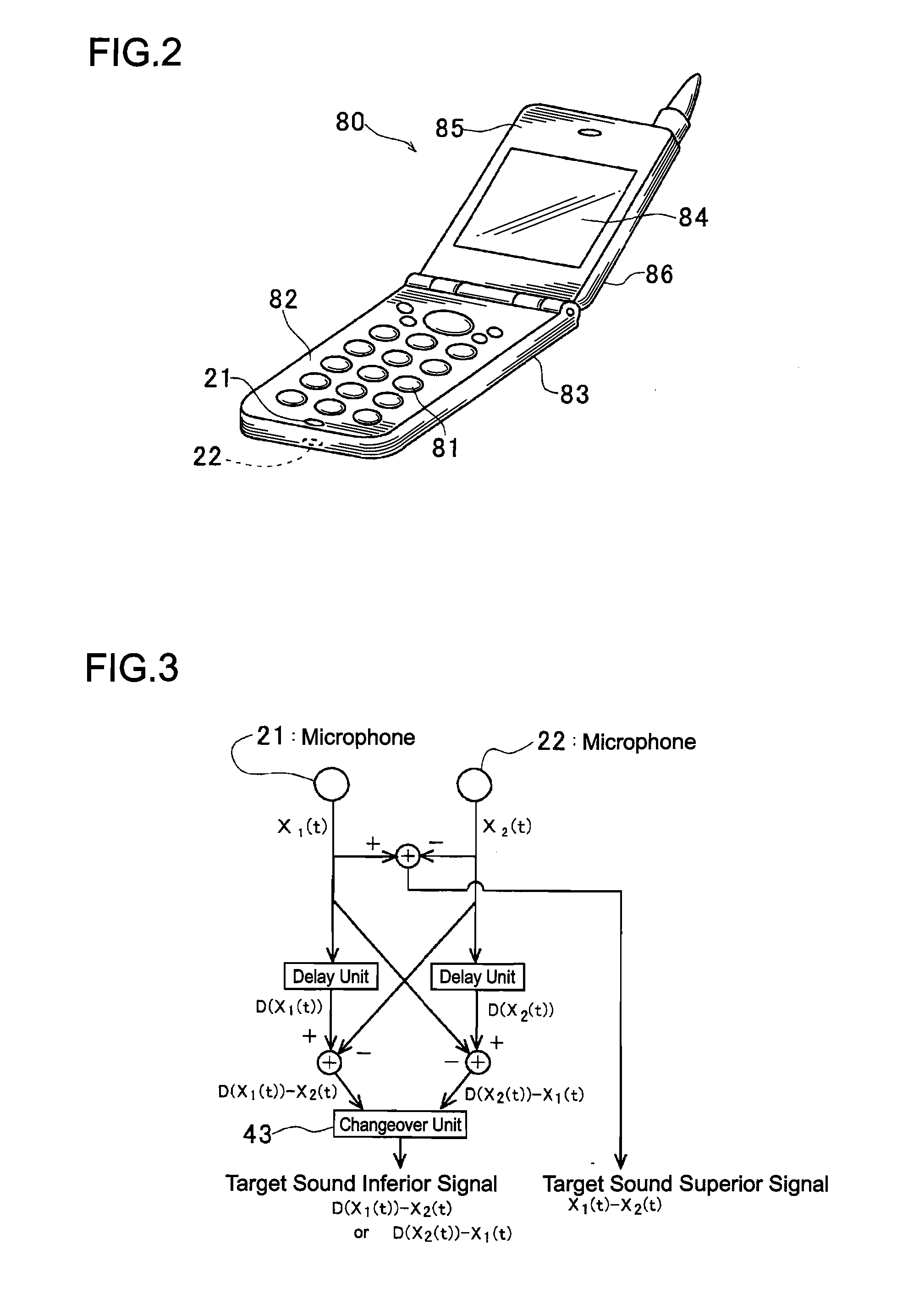
[0258]FIG. 1 illustrates the general structure of a sound source separation system 10 according to the first embodiment of the invention. FIG. 2 illustrates the structure of a cellular phone 80 equipped with the sound source separation system 10. FIG. 3 illustrates the structure of a part of the sound source separation system 10 that performs directivity control. FIG. 4 is an explanatory diagram for a portion that generates a first target sound inferior signal in the part that performs directivity control in FIG. 3. FIG. 5 illustrates the directional characteristics of a target sound superior signal and the first target sound inferior signal used in a normal mode, FIG. 6 illustrates the directional characteristics of the target sound superior signal and second target sound inferior signal used in a changeover mode, and FIG. 7 illustrates directional characteristics with FIGS. 5 and 6 spread out to take a horizontal axis as a direction (angle) θ. FIG. 8 is an explanatory diagram for ...

second embodiment

[0293]FIG. 9 illustrates the general structure of a sound source separation system 200 according to the second embodiment of the invention. FIG. 10 illustrates directional characteristics of a target sound superior signal and target sound inferior signal, and FIG. 11 illustrates directional characteristics with FIG. 10 spread out to take a horizontal axis as a direction (angle) θ. The sound source separation system 200 of the second embodiment is a system relating to .

[0294]With reference to FIG. 9, the sound source separation system 200 comprises two microphones 221, 222, disposed in such a manner as to be spaced away, a target sound superior signal generator 230 which generates a target sound superior signal by performing a linear combination process for emphasizing a target sound on a time domain using the received sound signals of the two microphones 221, 222, a target sound inferior signal generator 240 which generates a target sound inferior signal to be paired with the target...

third embodiment

[0310]FIG. 12 illustrates the general structure of a sound source separation system 300 according to the third embodiment of the invention. FIG. 13 illustrates the respective directional characteristics of first and second target sound superior signals and target sound inferior signal, and FIG. 14 illustrates directional characteristics with FIG. 13 spread out to take a horizontal axis as a direction (angle) θ. The sound source separation system 300 of the third embodiment is a system relating to .

[0311]With reference to FIG. 12, the sound source separation system 300 comprises two microphones 321, 322 disposed as to be spaced away from each other, a target sound superior signal generator 330 that generates first and second target sound superior signals by performing a linear combination process for emphasizing a target sound on a time domain using the received sound signals of the two microphones 321, 322, a target sound inferior signal generator 340 that generates a target sound i...


PUM


Abstract

The invention provides a sound source separation system, a sound source separation method, and an acoustic signal acquisition device which can precisely separate a target sound and a disturbance sound coming from an arbitrary direction, and which ensures miniaturization of a device. A sound source separation system 10 comprises two microphones 21, 22 disposed side by side in a direction in which a target sound comes from, a target sound superior signal generator 30 which performs a linear combination process for emphasizing the target sound, using the received sound signals of the microphones to generate a target sound superior signal, a target sound inferior signal generator 40 which performs a linear combination process for suppressing the target sound, using the received sound signals of the microphones 21, 22, to generate a target sound inferior signal, and a separation unit 60 which separates the target sound and a disturbance sound, using a target sound superior signal spectrum and a target sound inferior signal spectrum.

Description

CROSS-REFERENCE TO PRIOR APPLICATION[0001]This is the U.S. National Phase Application under 35 U.S.C. §371 of International Patent Application No. PCT / JP2005 / 022466 filed Dec. 7, 2005, which claims the benefit of Japanese Patent Application No. 2004-366202 filed Dec. 17, 2004, and Japanese Patent Application No. 2005-270931 filed Sep. 16, 2005. The International Application was published in Japanese on Jun. 22, 2006 as WO 2006 / 064699 A1 under PCT Article 21(2).TECHNICAL FIELD[0002]The present invention relates to a sound source separation system, a sound source separation method and an acoustic signal acquisition device which separate a target sound and a disturbance sound coming from an arbitrary direction other than a direction from which the target sound comes, and is available for a case where a desired speech is acquired through a portable device like a cellular phone, and an in-vehicle device like a car navigation system.BACKGROUND ART[0003]In normal voice recognition, a speec...

Claims


Application Information

Patent Timeline
IPC IPC(8): G10K11/16H04R3/00
CPCH04R2499/11H04R1/406
Inventor KOBAYASHI, TETSUNORIAKAGIRI, KENZOKANBA, SATOSHI
Owner WASEDA UNIV
Why Eureka
Try Eureka