Abrasive Wire Sawing

Active Publication Date: 2007-12-13
REC SOLAR
View PDF11 Cites 37 Cited by
  • Summary
  • Abstract
  • Description
  • Claims
  • Application Information

AI Technical Summary

Benefits of technology

[0013] It is proposed that two or more grooved pulley wheels are introduced into the centre of the web such that the wire is picked up as it emerges from one of the four driven wire roller guides and by-passes the next two subsequent rollers, to be re-introduced to the grooves of the fourth

Problems solved by technology

However, this is not always the case, and in certain circumstances it is important that any region of the material which is not in a condition to produce commercially acceptable wafers, (because of defects in its chemical, physical, or electronic properties), is not sawn because this will convert up to 50% of the material into unrecoverable saw-dust which might otherwise be retained for subsequent recycling.
Whilst this would appear to maximize machine capacity utilisation, it has been found to have considerable drawbacks.
The casting process used commercially to manufacture the silicon ingots results in the production of unacceptable quality material in both the bottom and top few centimetres of the blocks.
It is inevitable that one

Method used


Image

  • Abrasive Wire Sawing
  • Abrasive Wire Sawing
  • Abrasive Wire Sawing

Examples


Example

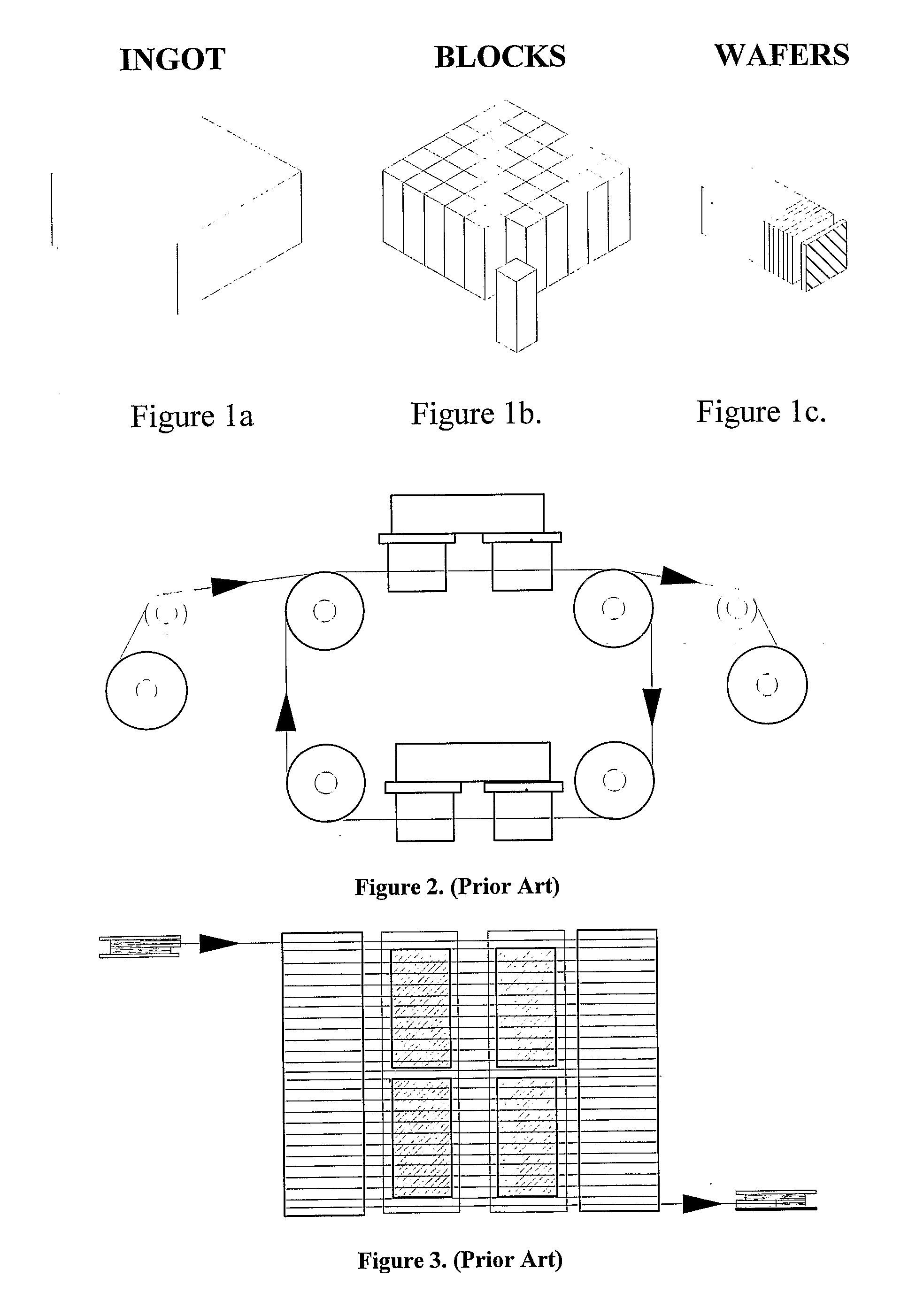
[0028] Production of thin wafers of semiconductor material is shown generally in FIG. 1. An ingot of silicon (shown in FIG. 1a) is cast in a crucible, and is allowed to cool slowly, to ensure an appropriate crystalline form. The ingot is cut by diamond saws into a series of tall blocks of uniform cross section (as shown in FIG. 1b). The blocks are then sawn into thin wafers using multibladed wire saws (as shown in FIG. 1c). The resultant wafers may be used to produce solar cells for the photovoltaic industry.

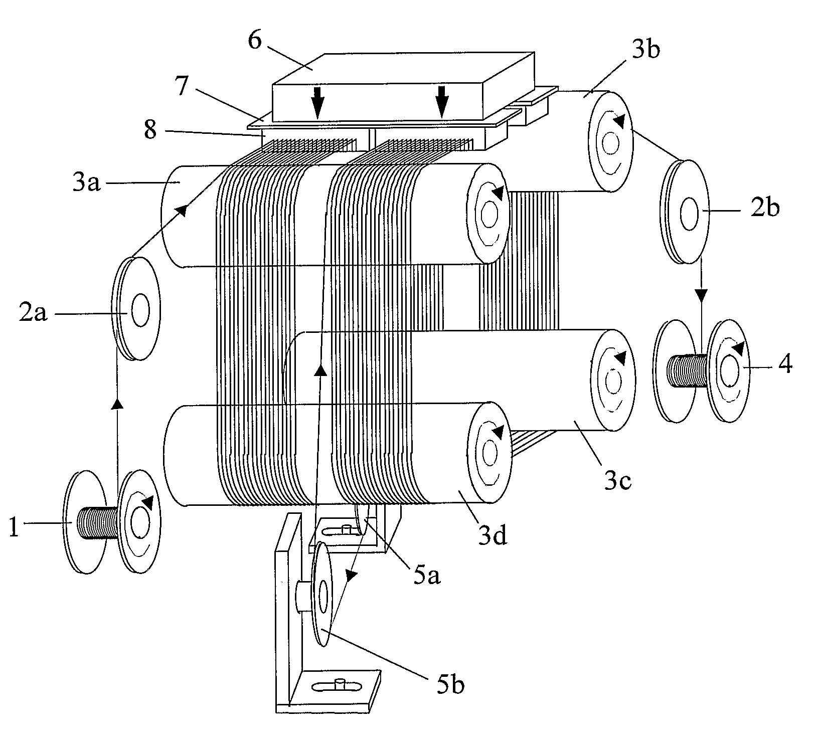
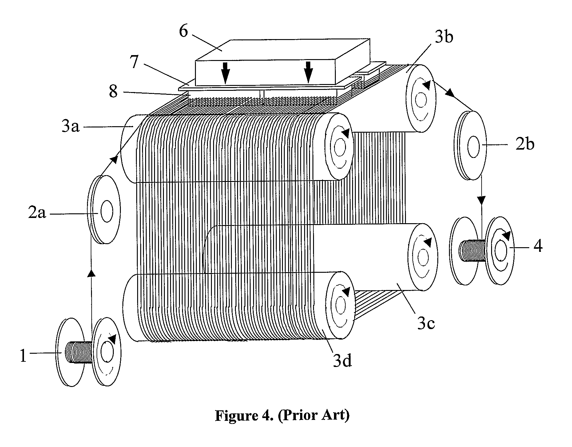
[0029] An example of a prior art wire saw is shown in FIGS. 2, 3 and 4. Four motor driven grooved roller guides are arranged in two pairs, one above the other. The two pairs are spaced vertically apart. A cutting wire is wound continuously round the roller guides at a very shallow pitch, to form a web with upper and lower cutting planes. Four blocks of silicon (e.g. four of the blocks shown in FIG. 1b) are disposed to be cut in the upper cutting plane, and four more blocks are ...


PUM

PropertyMeasurementUnit
Lengthaaaaaaaaaa
Tensile propertiesaaaaaaaaaa
Widthaaaaaaaaaa

Abstract

Apparatus for forming a multiplicity of thin wafers from at least two similar blocks, the apparatus comprising a supply reel (1) to supply wire, an upper pair of parallel spaced roller guides (3a,3b) having a multiplicity of circumferential grooves on their surfaces, a lower pair of parallel spaced roller guides (3c,3d) having a similar multiplicity of circumferential grooves on their surfaces and spaced apart from the upper pair of roller guides in a plane generally parallel to and spaced apart from a plane defined by the axes of the upper pair of roller guides, and a collection reel (2); the arrangement being such that a wire from the supply reel can pass around successive grooves along the roller guides from near the supply reel to near the collection reel, so to form a four sided continuous web of wires along the length of the roller guides and means to drive the wire rapidly from the supply reel to the collection reel, and means to move the blocks (4) through the web of wire between the pairs of roller guides in a direction generally perpendicular to the axes of the roller guides, so that the blocks are cut into wafers by the action of the moving wire and an abrasive slurry,
in which part way along the roller guides, the wire is diverted around at least two pulley wheels (6a,6b) to remove the wire from the web after it has passed over a roller guide at a predetermined point, and to reintroduce the wire into the web via a subsequent roller guide at a point laterally displaced from the point at which it left the web, so that there is a gap (7) in the web of wire which divides the web into two separate sections, and no cutting action can occur in that gap.

Description

TECHNICAL FIELD OF THE INVENTION [0001] The invention relates to an apparatus for abrasive wire sawing, and to a method of abrasive wire sawing. BACKGROUND OF THE INVENTION [0002] The technique of multi-blade abrasive wire sawing has been in commercial use for several years. The process is used when it is required to slice thin plates or wafers from bars or blocks of expensive and fragile semiconductor or electro-optic materials. [0003] In the standard process a high tensile steel wire of 150 to 180 microns diameter, which may or may not be coated with a layer of a softer material such as brass, is taken from a supply reel which can contain 200 km. or more of the wire, and passed under tension round a series of four motor driven wire guide rollers before being taken up on a collection reel. The surface of each of the wire guide rollers has a series of closely spaced ‘V’ shaped grooves machined in it at a pitch separation equal to the thickness of the wire plus the thickness of the r...

Claims


Application Information

Patent Timeline
IPC IPC(8): B23D57/00B28D5/04
CPCB23D57/0023B28D5/045B23D57/0061B28D5/0058B23D57/00B28D5/04
Inventor HUKIN, DAVID AINSWORTH
Owner REC SOLAR
Why Eureka
Try Eureka