Image processing method and image processing apparatus

Inactive Publication Date: 2005-06-09
PANASONIC CORP
View PDF5 Cites 20 Cited by
  • Summary
  • Abstract
  • Description
  • Claims
  • Application Information

AI Technical Summary

Benefits of technology

[0008] The present invention is made to solve the above-described problems and has for its object to provide an image processing method and an image processing apparatus for determining an appropriate threshold value for each local area of a multiple gray-level image, and obtaining, using this threshold value, a binarized image in which an object can be accurately separated from a background.

Problems solved by technology

In this method, however, uneven lighting or the like may cause a portion of the background area to be “0” and undesirably recognized as a character area, resulting in inaccurate reading of the characters.
As a result, it becomes difficult to separate the shot objects such as bacteria from the background to obtain accurate positions or number of the bacteria.
However, since the threshold value is determined on the basis of the average of the luminance values of the local areas, the average luminance value becomes small in an area where the density of objects to be separated from the background is high, and a lower threshold value is set, that is, an appropriate threshold value cannot be obtained, resulting in a possibility that a desired binarized image cannot be obtained.

Method used


Image

  • Image processing method and image processing apparatus
  • Image processing method and image processing apparatus
  • Image processing method and image processing apparatus

Examples


embodiment 1

[0042]FIG. 3 is a diagram for explaining the principle of an image processing method according to a first embodiment of the present invention, illustrating an original image 300 having three or more levels of gray, that is, a gray-scale original image, and histograms corresponding to local areas of the original image 300. An image obtained by shooting bacteria is used as the original image 300. A histogram 303 is a histogram of luminance values in a local area 301 of the original image 300.

[0043] The histogram 303 shows the luminance values of all pixels included in the local area 301 by their frequencies, and dark pixels, i.e., pixels whose luminance values are “0” are located at the left side of the image while bright pixels, i.e., pixels whose luminance values are “255”, are located at the right side of the image. The number of pixels indicating each luminance value is taken in the vertical axis. Since, in the local area 301, the background has the largest area, the number of pi...

embodiment 2

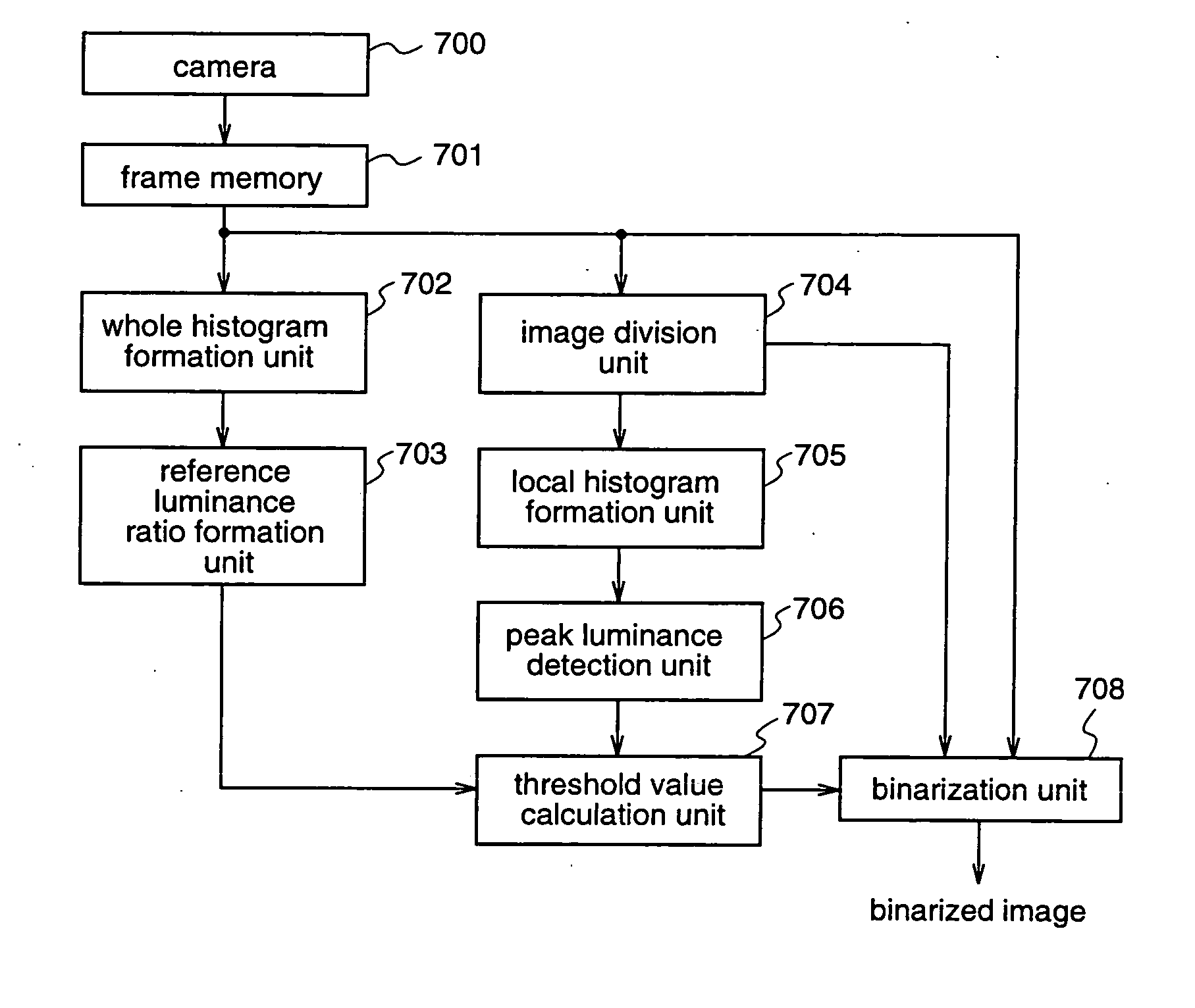
[0062]FIG. 7 is a block diagram illustrating an image processing apparatus according to a second embodiment of the present invention, for implementing the image processing method according to the first embodiment.

[0063] With reference to FIG. 7, an image taken by a camera 700 is stored in a frame memory 701. The taken image is a gray image comprising 1000×1000 pixels, each pixel having 256 levels of gray. The frame memory 701 outputs, as image data, the whole area of the stored image or a part of the image. In this second embodiment, the frame memory 701 outputs the whole area of the image.

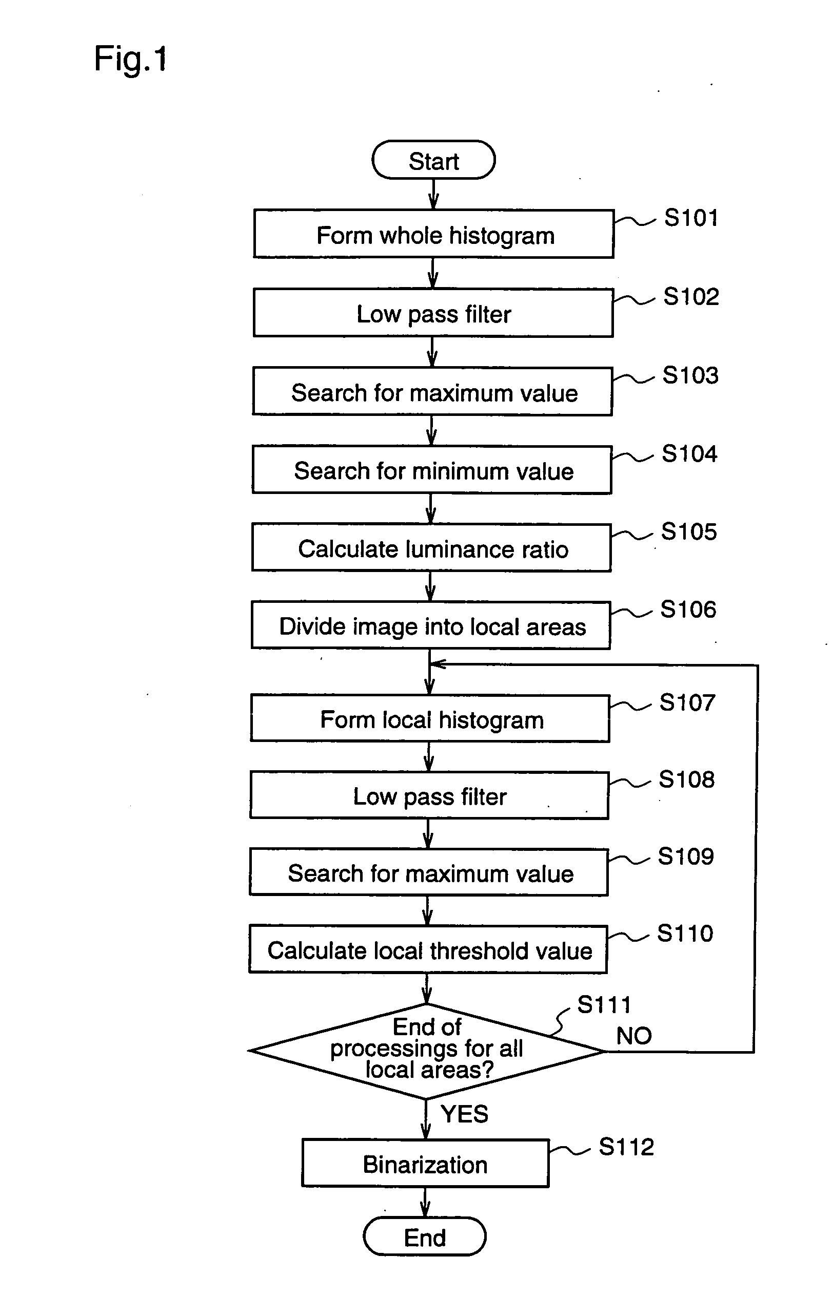
[0064] A whole histogram formation unit 702 forms a luminance histogram of the whole image data outputted from the frame memory 701, as shown in steps S101 and S102 of the first embodiment.

[0065] A reference luminance ratio formation unit 703 obtains, as a reference luminance value G, a luminance value indicating a maximum frequency of the luminance histogram that is formed by the whole histogr...


PUM


Abstract

An image processing method comprises forming a histogram of an entire image, determining a ratio between a reference luminance value and a reference threshold value at a maximum frequency, dividing the image into local areas, forming a histogram of each local area, determining a luminance value at a maximum frequency, multiplying this luminance value by the ratio between the reference luminance value and the reference threshold value to obtain a threshold value of the local area, and performing binarization for the local area using the threshold value. Therefore, it is possible to determine an appropriate threshold value in each local area of a multiple gray-level image, and obtain, using this threshold value, a binarized image which enables accurate separation of an object from a background.

Description

FIELD OF THE INVENTION [0001] The present invention relates to an image processing method and an image processing apparatus for performing binarization to convert image data of multiple gray levels, which is obtained by shooting an object with a common digital camera, into binarized image data. BACKGROUND OF THE INVENTION [0002] For example, as a pretreatment of an OCR (Optical Character Reader), binarization must be carried out, that is, characters written on a paper are read by a camera or a scanner as image data having multiple gray levels not less than three, i.e., as a gray-scale image, and thereafter, the image is separated into a character area and a background area. In this case, using a predetermined threshold value as a reference, a portion having a gray level larger than the threshold value, i.e., a light portion, is converted into “1” as a paper area to be a background, and a portion having a gray level equal to or smaller than the threshold value, i.e., a dark portion, ...

Claims


Application Information

Patent Timeline
IPC IPC(8): H04N1/40G06V10/28H04N5/57
CPCG06K9/38G06V10/28H04N5/57
Inventor TAKARADA, SHINICHI
Owner PANASONIC CORP
Why Eureka
Try Eureka