Angular velocity sensor having one amplifying circuit for amplifying plural detection signals

a technology of angular velocity and amplifier circuit, applied in the field of angular velocity sensors, can solve the problems of complex circuit, large circuit size, difficult to prevent circuit from becoming complicated and large-sized

Inactive Publication Date: 2008-11-04
SEIKO INSTR INC
View PDF5 Cites 32 Cited by
  • Summary
  • Abstract
  • Description
  • Claims
  • Application Information

AI Technical Summary

Benefits of technology

[0016]Accordingly, it is an object of the present invention to provide an angular velocity sensor which can, after amplifying a plurality of detection signals using one amplifying circuit, properly separate these detection signals without providing a plurality of signal sources.
[0024]According to the present invention with the use of the combination of the phase division processing and the time division processing, it is possible to properly perform the separation processing of the combined signals after amplification. Accordingly, it is possible to simultaneously perform the amplifying processing of the output of the first detection circuit, the output of the second detection circuit and the output of the third detection circuit using one amplifying circuit.

Problems solved by technology

The number of amplifiers for such signals is increased along with the increase of the number of detection axis of the mechanical dynamic quantities and hence, there is observed a tendency that a circuit becomes complicated and large-sized with respect to a multiple-axis detection type sensor.
In this manner, it is difficult to prevent the circuit from becoming complicated and large-sized with the provision of the plurality of signal sources.

Method used


Image

  • Angular velocity sensor having one amplifying circuit for amplifying plural detection signals
  • Angular velocity sensor having one amplifying circuit for amplifying plural detection signals
  • Angular velocity sensor having one amplifying circuit for amplifying plural detection signals

Examples


first modification

(First Modification)

[0206]Next, the first modification of the above-mentioned angular velocity sensor is explained.

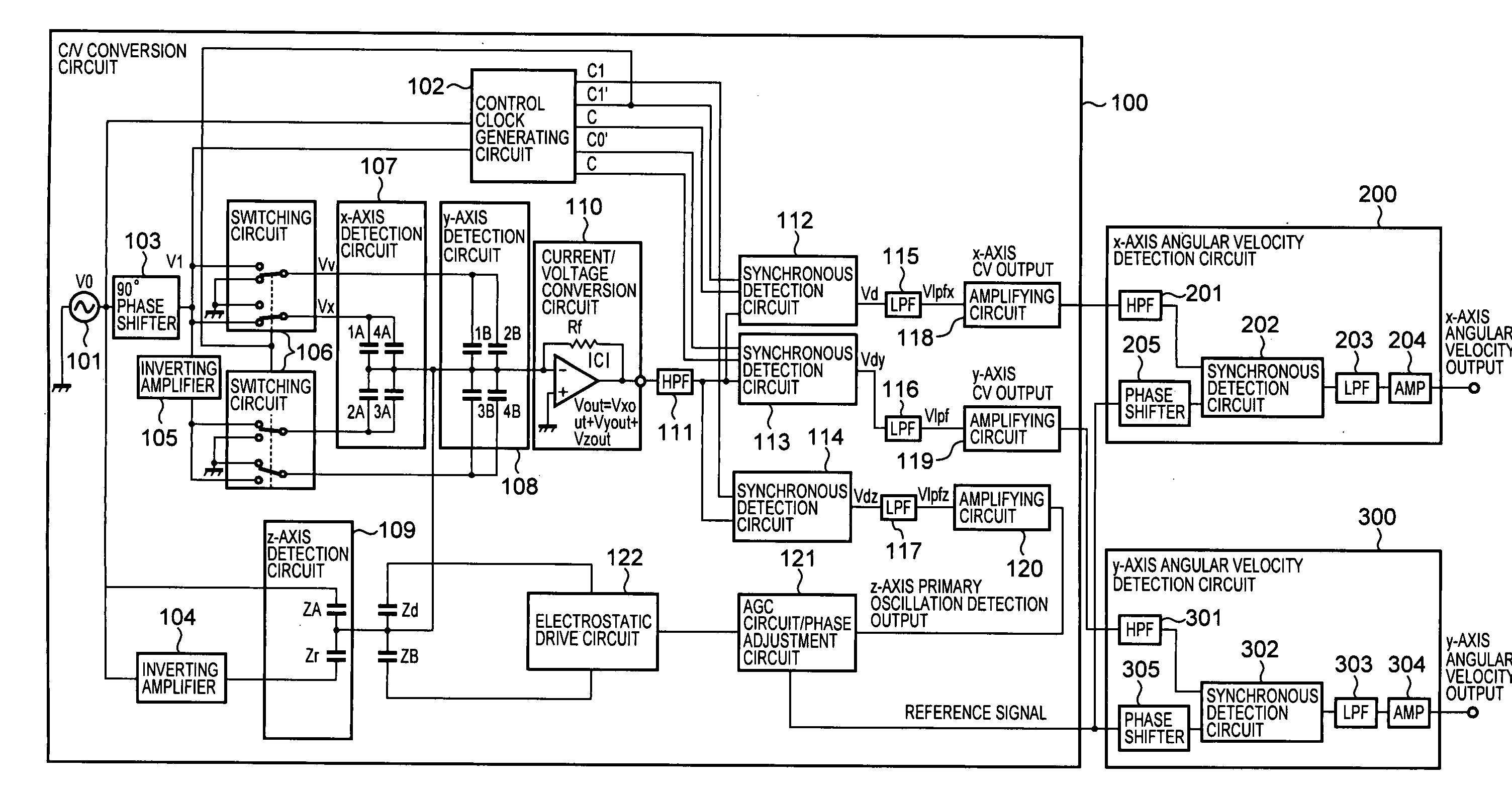
[0207]The first modification is characterized by a C / V conversion circuit 100 which is provided for suppressing the generation of crosstalk (interference with cross axis). That is, the C / V conversion circuit 100 performs processing which includes a non-detection time in time division in which a Vxout signal and a Vyout signal which are formed by division using a time division method are not detected (extracted).

[0208]In the above-mentioned time division processing shown in FIG. 5, the Vyout signal is outputted during an OFF period of the Vxout signal, and the Vxout signal is outputted during an OFF period of the Vyout.

[0209]However, when a response possible band of a current / volume conversion circuit 110 is insufficient, for example, when a limit of a high frequency band is restricted to a low value, as shown in FIG. 10, signal waveform becomes rounded thus giving rise ...

second modification

(Second Modification)

[0225]Next, the second modification of the above-mentioned angular velocity sensor is explained.

[0226]FIG. 8 is a circuit block diagram showing a C / V conversion circuit 100 of the second modification.

[0227]Here, parts identical with the constitution of the parts of the above-mentioned angular velocity sensor are given the same symbols and their detailed explanation is omitted. That is, in this modification, the parts different from the parts of the above-mentioned angular velocity sensor are explained.

[0228]In the angular velocity sensor according to the above-mentioned embodiment, the x axis detection circuit 107 is formed using capacitors 1A to 4A and the y detection circuit 108 is formed using capacitors 1B to 4B. That is, the x axis detection circuit 107 and the y axis detection circuit 108 are formed using eight capacitors.

[0229]That is, the angular velocity sensor of the second modification is characterized by providing, in place of the x axis detection ci...

third modification

(Third Modification)

[0252]Next, a third modification of the above-mentioned angular velocity sensor is explained.

[0253]The third modification is characterized by a C / V conversion circuit 100 which performs processing which provides a non-detection time in which a Vzout signal which is separated by phase division processing is not detected for suppressing the generation of crosstalk (the interference with cross axis) between detection signals of the x axis and the y axis, that is, the detection signals of the angular velocities and the detection signal of the z axis.

[0254]As described above, in the above-mentioned time division processing of the angular velocity components shown in FIG. 5 and FIG. 7, the Vxout signal and the Vyout signal are alternately outputted.

[0255]However, when a response possible region of a current / voltage conversion circuit 110 is insufficient, for example, when a limit of a high frequency band is low, at timing of switching the signal during time division pr...


PUM


Abstract

An angular velocity sensor amplifies a plurality of detection signals using one amplifying circuit and separates these detection signals after amplification. The angular velocity sensor detects displacements of a mass in the axial directions using x-, y- and z-axis detection circuits. A carrier wave whose phase is shifted 90° from that of a carrier wave of the z-axis detection circuit is applied to the x- and y-axis detection circuits and outputs of the axis detection circuits are collectively inputted to a current / voltage conversion circuit which outputs a combined signal to three synchronous detection circuits that separate the signal into x-, y- and z-axis detection signal components. In the synchronous detection circuits, by applying phase division processing to the combined signal, the z-axis detection signal component is separated from cross axis detection signal components and by applying time division processing to the signal components based on switching timing of the carrier wave, the x- and y-axis detection signal components are separated from each other.

Description

BACKGROUND OF THE INVENTION[0001]1. Field of the Invention[0002]The present invention relates to an angular velocity sensor which detects angular velocity acting on an object, more particularly to an angular velocity sensor of an electrostatic capacitance detection type which detects the angular velocity acting on the object based on a change of an electrostatic capacitance.[0003]2. Description of the Related Art[0004]In wide fields including a camera-shake correction device of a video camera, an air back device for a vehicle and a posture control device of a robot, a mechanical dynamic quantity sensor such as an acceleration sensor or an angular velocity sensor is used.[0005]As such a mechanical dynamic quantity sensor, there has been known an electrostatic-capacitance-detection-type sensor which detects the displacement of a mass based on a change of electrostatic capacitance between an electrode mounted on a mass (a mass body) which constitutes a movable body and a fixed electrod...

Claims


Application Information

Patent Timeline
Patent Type & Authority Patents(United States)
IPC IPC(8): G01P9/04G01C19/56G01C19/5726
CPCG01C19/56G01P15/125G01P15/18G01P2015/0842
Inventor UCHIYAMA, TAKESHIYARITA, MITSUOEGAWA, AKIRA
Owner SEIKO INSTR INC
Why Eureka
Try Eureka