Rail walking trolley with lifting mechanism

A lifting mechanism and a traveling trolley technology, applied in the directions of transportation, packaging, storage devices, etc., can solve the problem of not being able to completely prevent rocking, and achieve the effect of preventing interference.

Active Publication Date: 2011-01-12
IHI CORP
View PDF6 Cites 6 Cited by
  • Summary
  • Abstract
  • Description
  • Claims
  • Application Information

AI Technical Summary

Problems solved by technology

[0010] However, even if the guide is provided, when the flat cable is detached from the guide due to swaying in the running direction, the flat cable sways in the depth direction, and the swaying in the depth direction cannot be completely prevented.
Therefore, there is a possibility that the flat cable may interfere with the storage rack

Method used


Image

  • Rail walking trolley with lifting mechanism
  • Rail walking trolley with lifting mechanism
  • Rail walking trolley with lifting mechanism

Examples


Embodiment 1

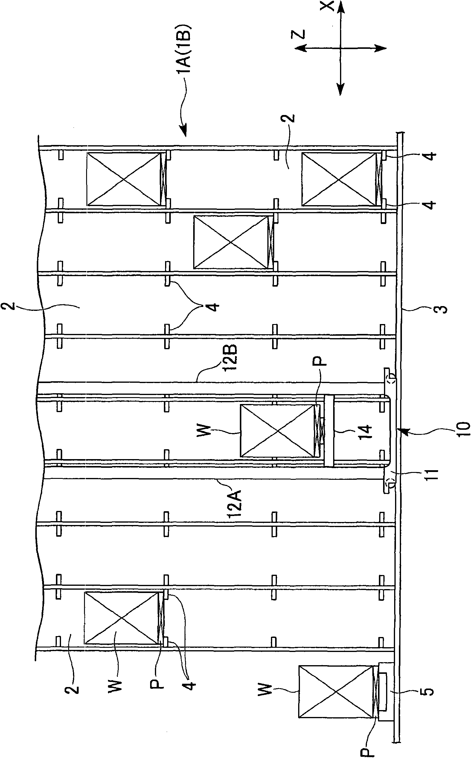
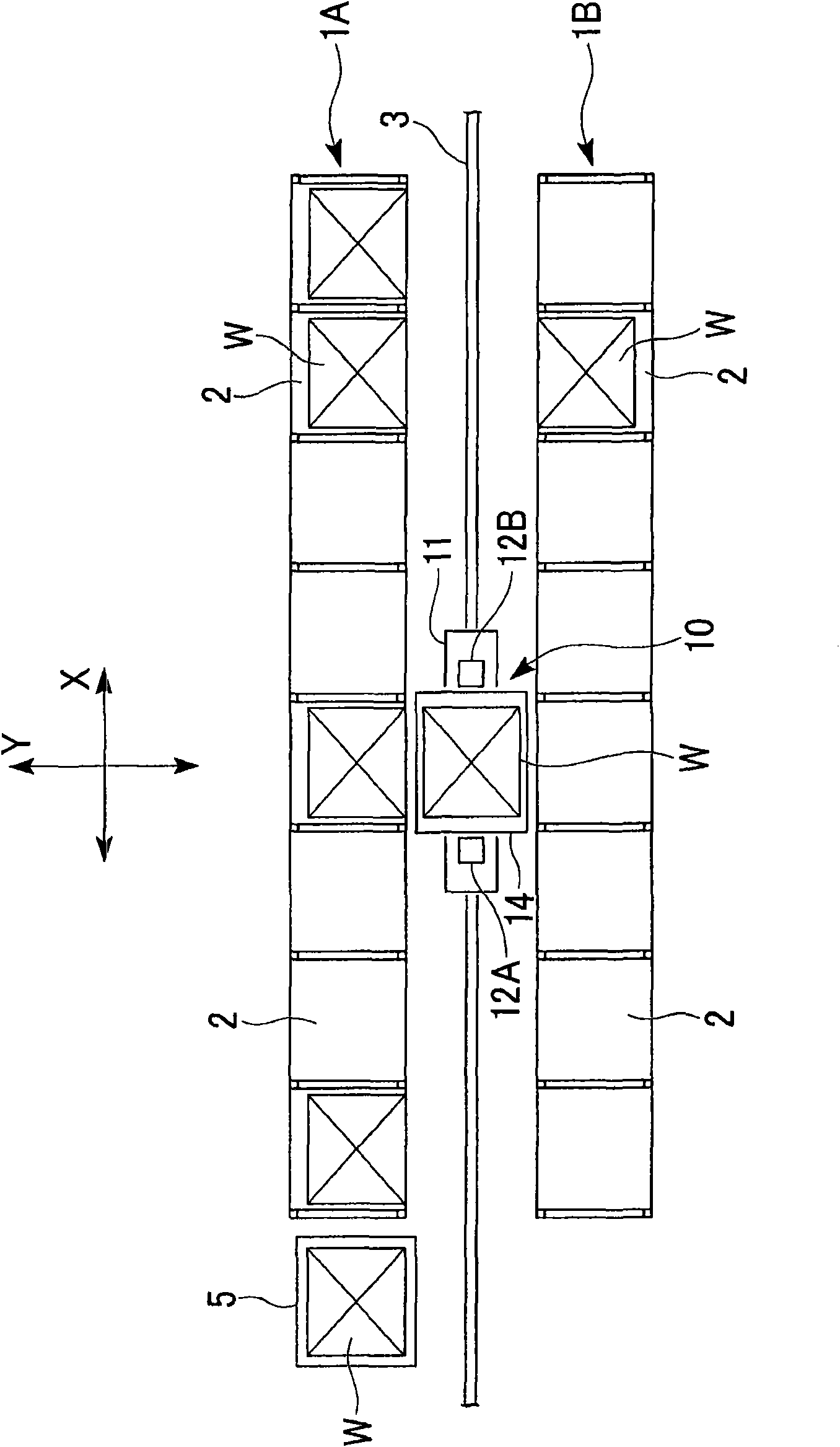
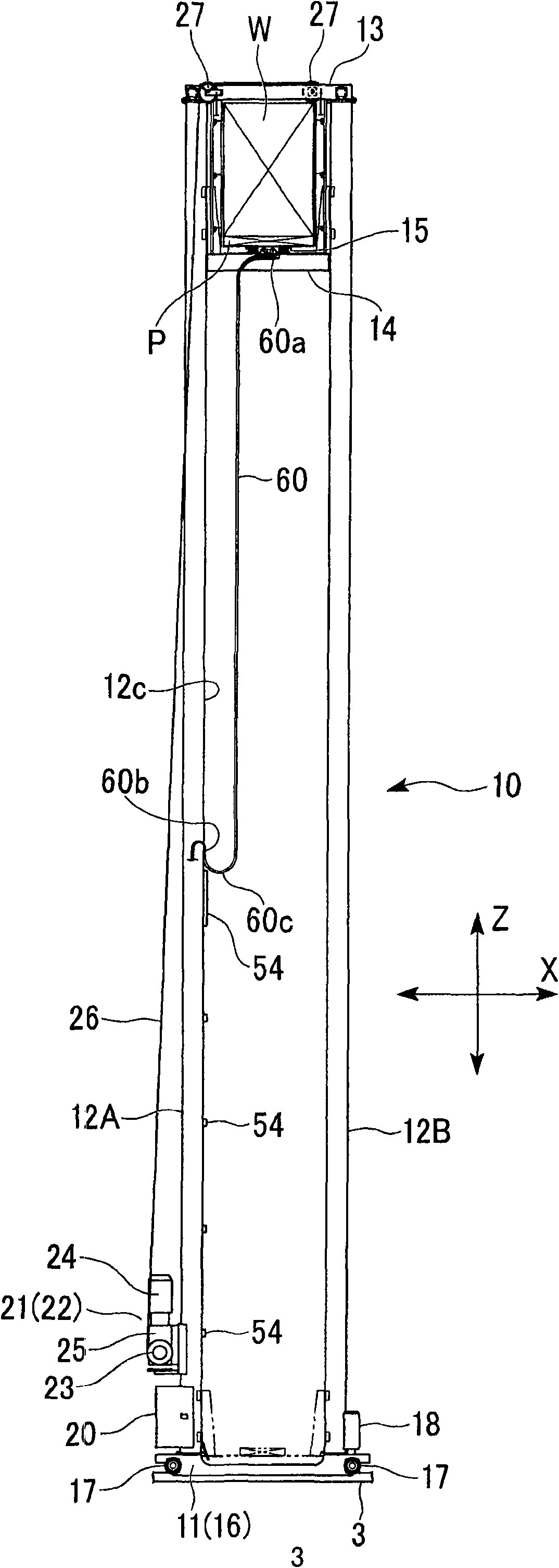
[0053] figure 1 as well as figure 2 It is a front view and a top view of the automatic warehouse equipment. The automatic warehouse equipment has two cargo storage racks 1A and 1B having a plurality of storage parts 2 in the horizontal direction and the up and down direction, and is arranged opposite to each other at a predetermined interval. Lay a guide rail (track) 3 in a straight line on the ground between the cargo storage racks 1A and 1B at positions equidistant from the two cargo storage racks 1A and 1B, and a tower crane (rail trolley with a lifting mechanism) 10 is set Be able to walk on this guide rail 3. The guide rail 3 is extended and laid to the loading and unloading platform 5 provided adjacent to the cargo storage racks 1A and 1B. In addition, the cargo storage racks 1A and 1B can also be called cargo storage racks having the multi-storey storage section 2 .

[0054] On both sides of the lower part of each storage part 2 of the cargo storage racks 1A, 1B, su...

Embodiment 2

[0100] Figure 12 It is a schematic plan view of the tower crane 10 of another second embodiment. The tower crane 100 is configured to run on two guide rails (rails) 3A, 3B arranged in parallel to each other.

[0101] The frame 116 of the trolley 111 has a rectangular frame shape in a plan view, and wheels 117 rolling on the guide rails 3A and 3B are provided at four corners thereof. On the Y-direction frame 116y of the frame 116, columns 112A, 112B are vertically fixed at positions equidistant from the guide rails 3A, 3B inside the frame 116 . The rack 114 is disposed inside the frame 116 of the trolley 111 and the columns 112A, 112B. That is, the rack 114 is arranged so as not to overlap with the trolley 111 in plan view.

[0102] In the tower crane 100 of this embodiment, although the rack 114 is raised and lowered along the columns 112A, 112B, it is the same as the previous embodiment, but since the rack 114 is arranged so that it does not overlap with the trolley 111 w...


PUM


Abstract

A tower crane is provided with a trolley which walks on a rail; an upright post which is uprightly arranged on the front part and the rear part of a walking direction of the trolley in approximately center of the direction which is orthognal to the walking direction of the trolley in a horizontal plane; a rack capable of lifting along the upright pose; a lifting mechanism for lifting the rack; and cable chains used for containing a plurality of cables connected with an electrical apparatus on the rack and assembled between the rack and an approximately center part at the height direction for concavely and deviously hanging downwards for changing the bending position of the rack. The cable chains are arranged at bottom of the rack relative to a fixing part at side of the rack; the cable chains are hung along the side opposite to the rack in the side of the upright post. And a specific length from the fixing part of the rack side to a linking part is formed by a first cable which has the characteristic of concavely bending upwards, and compared with the linking part, one side of the upright post is formed by a second cable which has the characteristic of concavely bending downwards.

Description

technical field [0001] The invention relates to a track traveling trolley with a lifting mechanism. [0002] This application claims the priority of Patent Application No. 2009-158061 filed in Japan on July 2, 2009 and Patent Application No. 2009-158062 filed in Japan on July 2, 2009, the contents of which are incorporated herein. Background technique [0003] The walking trolley with lifting mechanism is used when transporting heavy goods horizontally and vertically. For example, in an automatic warehouse in which goods are stored on storage racks in which a plurality of storage sections are arranged vertically and horizontally, the goods are transported using tower cranes. This tower crane is an example of a traveling trolley with a lifting mechanism. [0004] The tower crane is equipped with a trolley that runs on a rail that is horizontally and linearly arranged along the storage rack of the goods. Two columns are erected on the trolley, and an elevating mechanism is p...

Claims


Application Information

Patent Timeline
Patent Type & Authority Applications(China)
IPC IPC(8): B65G1/04
Inventor 天田弘之
Owner IHI CORP
Why Eureka
Try Eureka