Multi-tag identification method of RFID reader

An identification method and reader technology, applied in the field of radio frequency identification, can solve the problems of incorrectly identifying tags and wasting time, and achieve the effects of high recognition rate, improved reading speed, and increased number of reads

Inactive Publication Date: 2011-01-12
UNIV OF ELECTRONICS SCI & TECH OF CHINA
View PDF3 Cites 28 Cited by
  • Summary
  • Abstract
  • Description
  • Claims
  • Application Information

AI Technical Summary

Benefits of technology

This patented technology allows an improved way of identifying collars on documents based upon their content or other attributes such as size. By utilizing this technique, we have achieved better performance than previous methods like histograms analysis techniques. Additionally, our new approach includes two phases - Random Alignment (RA) phase followed by Binary Searching Phase(BSP). These improvements improve efficiency over existing algorithms while also reducing resource usage compared to older technologies.

Problems solved by technology

Technological Problem addressed in this patented technical problem relating to conventional methods involving radar systems involves collisions caused during the process of identifying objects accurately due to factors like distance and timing differences such as interference patterns generated by other devices. These issues lead to delays and decreased accuracy in recognizing and deciding whether any tags may match up incorrectly. Therefore, improvements involve dynamically selecting different timeslants among predetermined ones without increasing processing complexity while maintaining accurate matches detection performance.

Method used


Image

  • Multi-tag identification method of RFID reader
  • Multi-tag identification method of RFID reader
  • Multi-tag identification method of RFID reader

Examples


Embodiment Construction

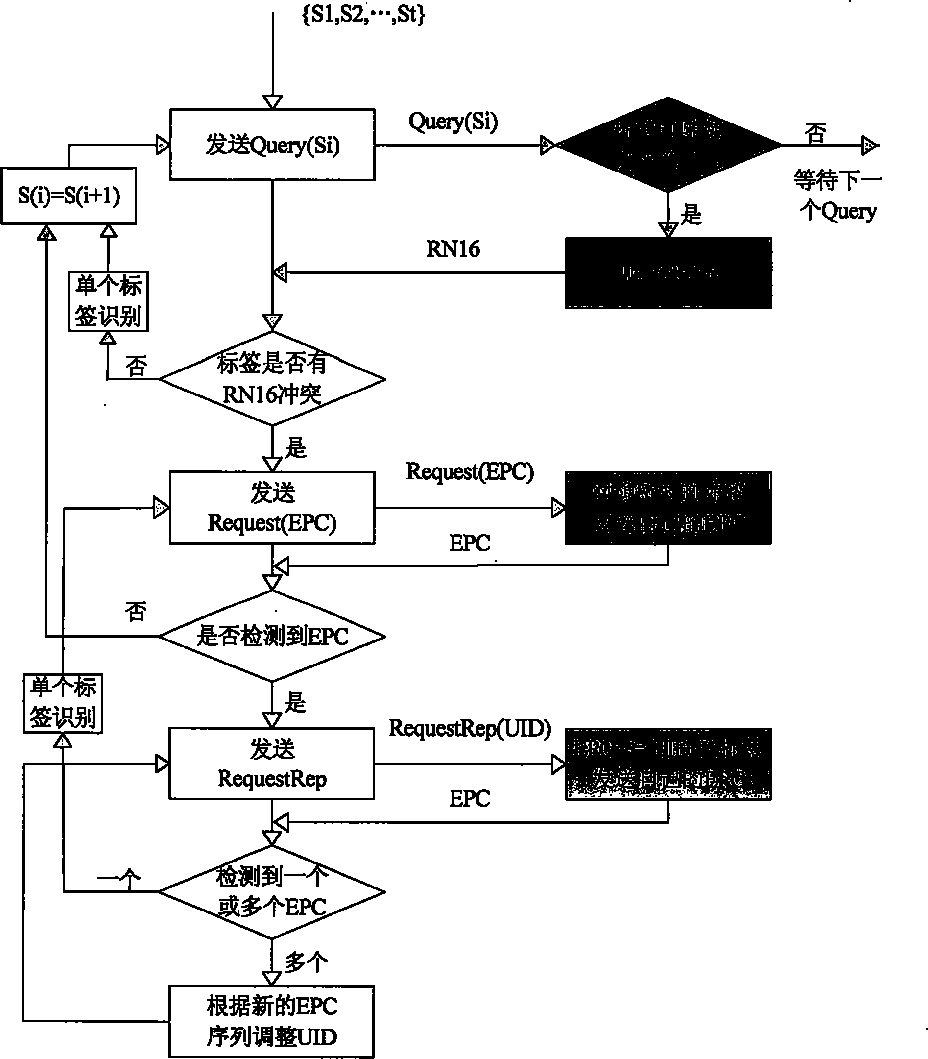
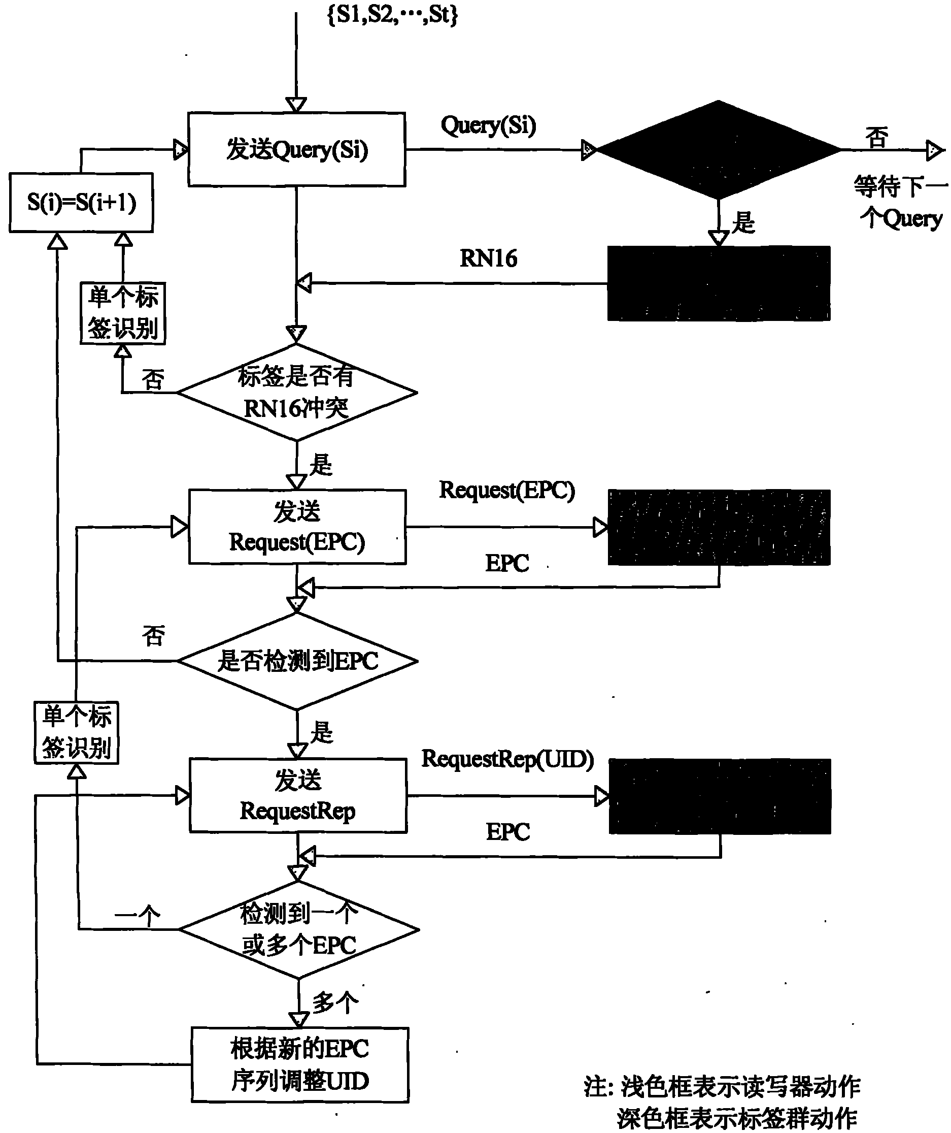
[0022] figure 2 It is a flowchart of the main steps of the identification method of the present invention. Block diagrams with a white background represent the actions of the reader; blocks with a gray background represent the actions of the tag. The present invention will be further described below in conjunction with accompanying drawing and specific embodiment:

[0023] A multi-tag identification method of an RFID reader is applied in an RFID system including an RFID reader and a plurality of tags. In this embodiment, we assume that there are 5 tags in the radio frequency area (RF Field) of the reader, and Set Q=7, then the time slot number is 0~(2 7 -1), that is, 0 to 127, including the following steps:

[0024] Step 1: The reader sends the detection command Detect(7) to the tag group. After the tag receives the detection command, it randomly starts from time slot 0 to time slot (2) Q In the time slot sequence of -1) (the value of Q is 7 in this embodiment), select on...


PUM


Abstract

The invention relates to a multi-tag identification method of an RFID reader. The method comprises the following steps: 1) a reader sends detection commands to a tag group, each tag randomly selects one time slot number from the time slot sequence ranging from 0 to 2Q-1 after receiving the detection commands and generates one binary data with 2Q-numbered bits as the time slot sequence of the corresponding tag; 2) after the reader receives the time slot sequences sent by the tags and detects the bit conflict of the time slot sequences of the tags; and 3) the reader begins to identify the tags according to a non-idle time slot number table entry and successively sends query commands Query (S1) to the tag group from small to large order of the slot sequences numbers. Thebeneficial effects of the invention are as follows: the invention inherits the high recognition rate characteristic of the binary tree algorithm, and combines the high identifying accuracy advantage of the binary tree algorithm and the fast identification advantage of the random aloha algorithm during the identification process of the tags.

Description


Claims


Application Information

Patent Timeline
Owner UNIV OF ELECTRONICS SCI & TECH OF CHINA
Why Eureka
Try Eureka