
Light-emitting diode device with compensating mechanism

A technology of light-emitting diodes and power control units, applied in the field of light-emitting diode devices with compensation mechanisms, can solve problems such as shortened product life, unstable current, and voltage fluctuations

Inactive Publication Date: 2011-01-12
UPEC ELECTRONICS CORP
View PDF2 Cites 7 Cited by
  • Summary
  • Abstract
  • Description
  • Claims
  • Application Information

AI Technical Summary

Problems solved by technology

[0006] In view of this, the purpose of the present invention is to provide a light-emitting diode device to solve the problem of shortened product life due to changes in illuminance and overheating of parts caused by voltage fluctuation or current instability when one LED is abnormal in the known technology. question

Method used


Image

  • Light-emitting diode device with compensating mechanism
  • Light-emitting diode device with compensating mechanism
  • Light-emitting diode device with compensating mechanism

Examples


Embodiment Construction

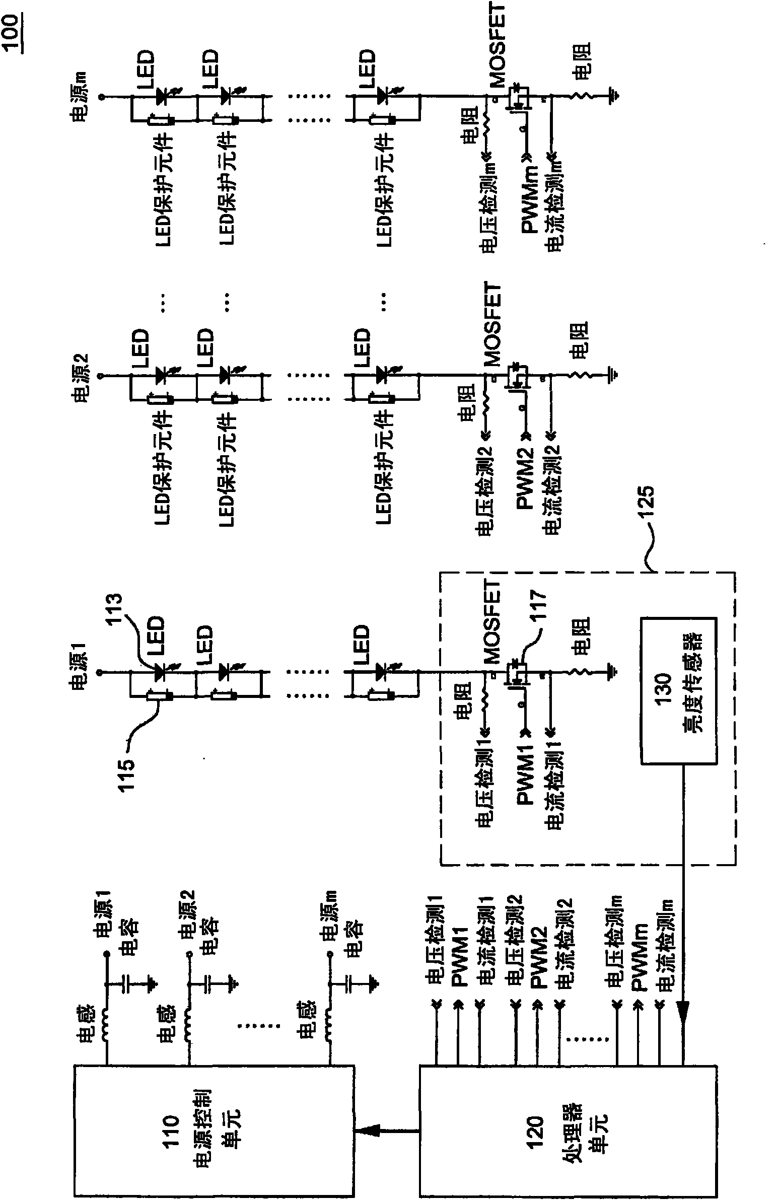
[0021] In order to further illustrate various embodiments, the present invention is provided with accompanying drawings. These drawings are a part of the disclosure of the present invention, which are mainly used to illustrate the embodiments, and can be combined with the relevant descriptions in the specification to explain the operating principles of the embodiments. With reference to these contents, those skilled in the art should understand other possible implementations and advantages of the present invention. Components in the drawings are not drawn to scale, and similar component symbols are generally used to denote similar components.

[0022] Embodiments of the light emitting diode device with compensation mechanism according to the present invention will be described below with reference to related drawings.

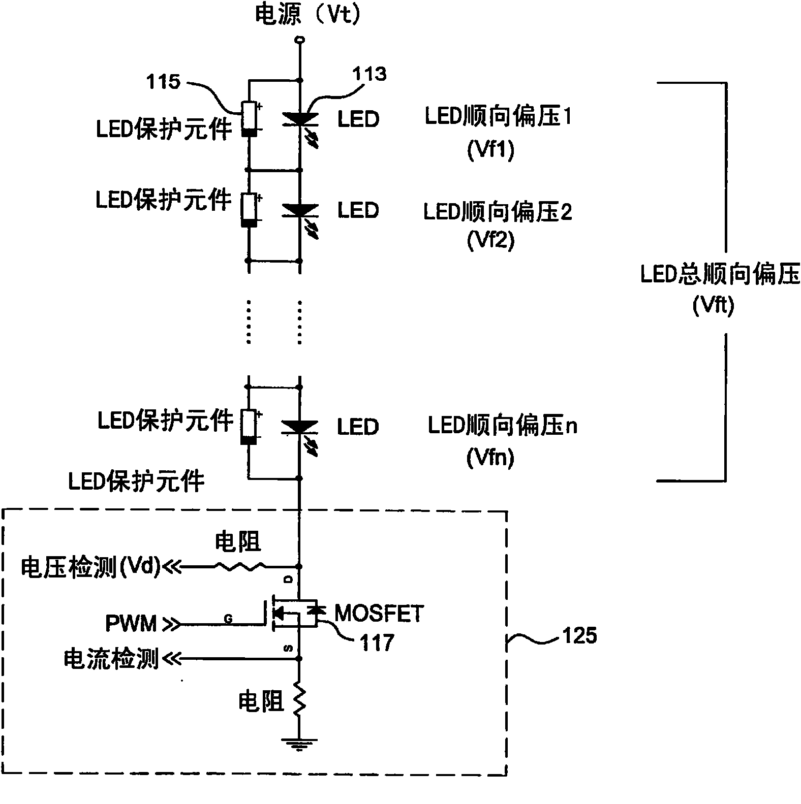
[0023] see figure 1 , which is a block diagram of an LED device with a compensation mechanism according to an embodiment of the present invention. In the fi...


PUM


Abstract

The invention discloses a light-emitting diode (LED) device. The LED device comprises a plurality of LEDs, a state detecting unit, a power supply control unit and a processor unit, wherein when more than one LEDs are out of order, the other LEDs can operate normally; the state detecting unit is coupled with the LEDs; the power supply control unit provides a power source and outputs the power source to the LEDs; and the processor unit instructs the power supply control unit to adjust the power source and output the power source to the LEDs according to the state signal provided by the state detecting unit. By using the light-emitting diode device with the compensating mechanism, the power can be rated.

Description

technical field [0001] The invention relates to a light emitting diode device, in particular to a light emitting diode device with a compensation mechanism. Background technique [0002] Light Emitting Diode (LED for short) was born in the 1960s, from red LED, green LED, all the way to blue LED, until 1998 did not really see the commercialization of LED. LEDs have functions such as power saving and fast switching speed. At present, LEDs are widely used in indication functions, and this field is also the first market for LEDs to enter, such as outdoor display boards, traffic lights, and flat lighting. As high-end mobile phones use LEDs as backlight sources, LEDs have opened up new application areas. [0003] The application range of LED is quite wide, from early mobile phones, small devices such as remote controls, etc., to the emergence of high-brightness LEDs in recent years, and the application range has expanded to products such as automobiles, lighting, and large outdoo...

Claims


Application Information

Patent Timeline
IPC IPC(8): H05B37/02H05B37/03F21V23/00F21Y101/02
Inventor 钟进淦黄书康吴政忠
Owner UPEC ELECTRONICS CORP
Learn More