Message speed limitation method, device and network equipment

A speed limiting device and message technology, applied in the field of network communication, can solve the problems of waste of CPU resources and poor practicability, and achieve the effect of improving the utilization rate

Inactive Publication Date: 2012-08-15
BEIJING XINWANG RUIJIE NETWORK TECH CO LTD
View PDF4 Cites 0 Cited by
  • Summary
  • Abstract
  • Description
  • Claims
  • Application Information

AI Technical Summary

Problems solved by technology

[0006] The present invention provides a message rate limiting method, device and network equipment, which are used to solve the problems that the existing hardware rate limiting method is poor in practicability, while the existing software rate limiting method will still cause additional waste of CPU resources and the like.

Method used


Image

  • Message speed limitation method, device and network equipment
  • Message speed limitation method, device and network equipment
  • Message speed limitation method, device and network equipment

Examples


Embodiment 1

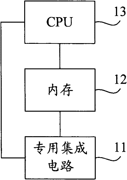
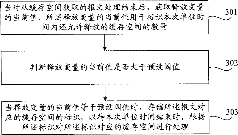
[0036] image 3 It is a flow chart of the packet rate limiting method provided by Embodiment 1 of the present invention. The execution subject of this embodiment is a communication device, combined with figure 1 shown in the structure, image 3 The packet rate limiting method in this embodiment shown includes:

[0037] Step 301, after the processing of the message obtained from the cache space is completed, obtain the current value of the release variable, and the current value of the release variable is used to identify the amount of cache space that is still allowed to be released per unit time;

[0038] Wherein, the release variable represents the amount of cache space that is allowed to be released per unit time, and the value of the release variable changes with time (actually, it refers to the release of the cache space). Specifically, when the CPU in the communication device determines that the current acquired location is valid according to the validity identifier i...

Embodiment 2

[0045] Figure 4 It is a flow chart of the packet rate limiting method provided by Embodiment 2 of the present invention. This embodiment can be implemented based on the first embodiment, and the similarities thereof will not be repeated here. Such as Figure 4 As shown, the message rate limiting method in this embodiment includes:

[0046] In step 401, the CPU acquires the message from the cache space, sends the message to the software processing module for processing, and moves the acquired position to the next cache space.

[0047] Step 402, the software module of the CPU processes the message, and releases the cache space after the message is processed.

[0048] In step 403, the message processing ends, and the CPU obtains the current value of the released variable, and judges whether the current value of the released variable is 0; wherein, in this embodiment, the preset threshold is taken as 0. When the judgment result is that the current value of the released variab...

Embodiment 3

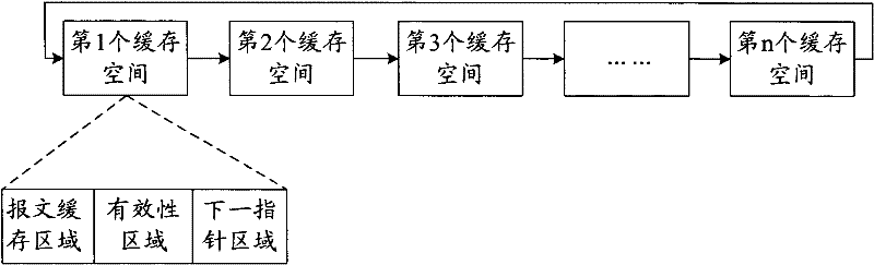
[0056] Figure 5a A flow chart of a method for obtaining the initial value of the release variable provided in Embodiment 3 of the present invention; Figure 5b It is a flow chart of another method for obtaining the initial value of the released variable provided by Embodiment 3 of the present invention. Specifically, in this embodiment, the initial value of the release variable is obtained according to the preset packet rate limit rate and the number of invalid buffer spaces in the packet receiving ring. Wherein, the invalid cache space refers to the cache space whose validity flag is invalid in the acquired packet receiving ring when the technical solution of the present invention is about to be implemented. Wherein, the timing for implementing the technical solution of the present invention may be when the communication device is in an initial state or in a non-initial state. Wherein, if the communication device executes the technical solution of the present invention in ...


PUM


Abstract

The invention discloses message speed limitation method, device and network equipment. The message speed limitation method comprises the following steps of obtaining a current value of a release variable after finishing treatment on a message obtained from a buffer space, wherein the current value of the release variable is used for marking an amount of the buffer space which is still allowed to be released within a current unit time; judging whether the current value of the release variable is larger than a preset threshold; and if the current value of the release variable is equal to the preset threshold, storing a mark of the buffer space corresponding to the message so as to treat the buffer space corresponding to the mark according to the mark after the current unit time is up. Basedon the technical scheme, speed limitation of the message is realized by limiting the release amount of the buffer space, and the device has the advantages of strong adaptability and capability of enhancing the CPU utilization ratio.

Description

technical field [0001] The invention relates to network communication technology, in particular to a message rate limiting method, device and network equipment. Background technique [0002] In order to manage embedded communication devices such as switches and support communication protocols, ASICs of communication devices need to send management messages with management functions and protocol messages for protocol processing to the central processing unit (CPU) of communication devices. Unit; referred to as: CPU), so that the CPU can perform software processing on the management message and the protocol message; similarly, the CPU will also send the management message and the protocol message through the application-specific integrated circuit. [0003] Wherein, receiving a message by the CPU of the communication device is generally referred to as receiving a packet (a packet refers to a message). based on figure 1 The partial circuit structure of the shown communication...

Claims


Application Information

Patent Timeline
Patent Type & Authority Patents(China)
IPC IPC(8): H04L12/56H04L47/21
Inventor 陈涛
Owner BEIJING XINWANG RUIJIE NETWORK TECH CO LTD
Why Eureka
Try Eureka