
Energy-saving motor with speed limiting function for new energy automobile

A new energy vehicle, energy-saving technology, applied in the direction of electric vehicles, current collectors, electromechanical devices, etc., can solve the problems of poor safety, increased motor loss, and reduced motor service life. efficiency effect

Inactive Publication Date: 2021-05-28
杨海军
View PDF0 Cites 0 Cited by
  • Summary
  • Abstract
  • Description
  • Claims
  • Application Information

AI Technical Summary

Problems solved by technology

[0004] Existing new energy vehicles mainly rely on motor drive to operate. The speed of the motor controls the running speed of the new energy vehicle. However, when the motor rotates rapidly for a long time, it is easy to increase the loss of the motor and reduce the service life of the motor. New energy vehicles are less safe

Method used


Image

  • Energy-saving motor with speed limiting function for new energy automobile
  • Energy-saving motor with speed limiting function for new energy automobile
  • Energy-saving motor with speed limiting function for new energy automobile

Examples


Embodiment 1

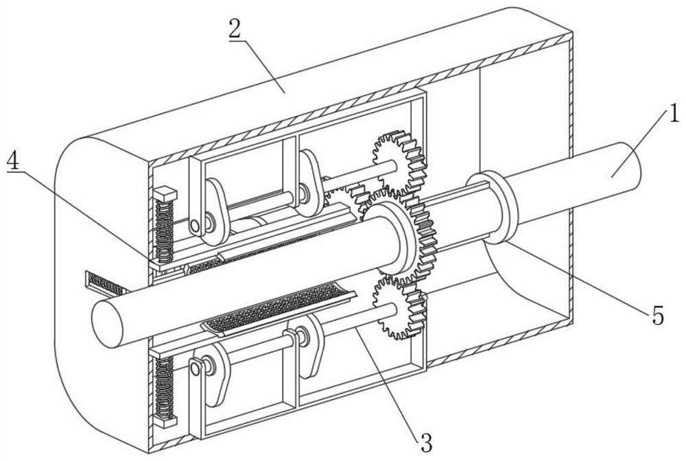
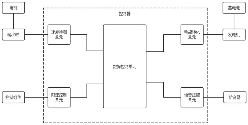
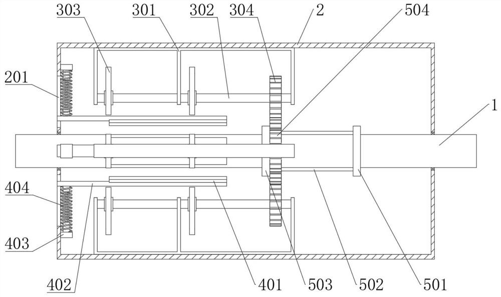
[0054] see Figure 1-11 , an energy-saving motor with a speed limiting function for new energy vehicles, including an output shaft 1 rotatably connected in a casing 2, and a plurality of matching speed limiting components 4 are arranged on the left side of the output shaft 1 to limit the speed. The outer end of the speed assembly 4 is provided with a matching intermittent assembly 3, the outer end of the output shaft 1 is connected with a control assembly 5, the control assembly 5 is located on the right side of the speed limiting assembly 4, and the control assembly 5 matches the intermittent assembly 3, The right end of the casing 2 is provided with a controller, and the controller is respectively connected with the output shaft 1 and the control assembly 5; please refer to Figure 8 and Figure 10 , the intermittent component 3 includes a connection seat 301, a plurality of circumferentially distributed connection seats 301 are fixedly connected in the housing 2, and the i...

Embodiment 2

[0068] see Figure 1-11 , where the same or corresponding components as those in Embodiment 1 use the corresponding reference numerals as in Embodiment 1, and for the sake of simplicity, only the differences from Embodiment 1 will be described below. The difference between this embodiment 2 and embodiment 1 is: please refer to figure 1 , the usage method of speed limiting component 4 is:

[0069] S1. The controller monitors the rotational speed of the output shaft 1;

[0070] S2. After detecting that the rotational speed of the output shaft 1 exceeds the limited speed, the control control assembly 5 is started;

[0071] S3. The control component 5 acts on the intermittent component 3 to make the intermittent component 3 rotate;

[0072] S4. The rotation of the intermittent component 3 drives the speed limiting component 4 to move, so that the speed limiting component 4 is intermittently in contact with the output shaft 1 to limit the speed of the output shaft 1 and reduce t...


PUM


Abstract

The invention discloses an energy-saving motor with a speed limiting function for a new energy automobile, which belongs to the field of new energy automobiles. The energy-saving motor with the speed limiting function for the new energy automobile comprises an output shaft rotationally connected in a shell, and a plurality of speed limiting assemblies matched with the output shaft are arranged on the left side of the output shaft; an intermittent assembly matched with the speed limiting assembly is arranged at the outer end of the speed limiting assembly, the outer end of the output shaft is connected with a control assembly, the control assembly is located on the right side of the speed limiting assembly, the control assembly is matched with the intermittent assembly, and speed limiting and adjustment can be effectively conducted on the output shaft through mutual cooperation of the controller, the intermittent assembly, the speed limiting assembly and the control assembly; the rotating speed of the motor is convenient to control, abrasion caused by long-time rapid rotation of the motor is effectively reduced, the service life of the motor is prolonged, the operation safety of the new energy automobile is improved, automatic control is effectively achieved, and the intelligent degree of the new energy automobile is improved.

Description

technical field [0001] The invention relates to the field of new energy vehicles, and more specifically, relates to an energy-saving motor with a speed limiting function for new energy vehicles. Background technique [0002] A car is a non-track-bearing vehicle driven by power and has 4 or more wheels, mainly used for: carrying people and (or) goods; towing vehicles carrying people and (or) goods; special purposes. With the increasing use of automobiles, there are various disadvantages in the currently widely used fuel engine automobiles. Statistics show that under the conditions of more than 80% of the roads, an ordinary car only uses 40% of the power potential. Dropped to 25%, more serious is the emission of waste gas pollution of the environment. Since the 1990s, countries all over the world have become increasingly vocal about improving environmental protection, and various electric vehicles have come to the fore. [0003] New energy vehicles refer to the use of unconv...

Claims


Application Information

Patent Timeline
Patent Type & Authority Applications(China)
IPC IPC(8): H02P3/04H02P3/06H02K7/116H02J7/00
CPCH02J7/00H02K7/116H02P3/04H02P3/06
Inventor 杨海军
Owner 杨海军
Learn More