
Rotating valve rotational speed control method for measuring-while-drilling tool

A technology of speed control and measurement while drilling, applied in construction and other directions, can solve problems such as unreported, unsatisfactory, and unconsidered, and achieve the effect of friendly application environment, reliable control route, and scientific control principle

Active Publication Date: 2018-03-13
CHINA UNIV OF PETROLEUM (EAST CHINA)
View PDF8 Cites 9 Cited by
  • Summary
  • Abstract
  • Description
  • Claims
  • Application Information

AI Technical Summary

Problems solved by technology

If the rotational speed of the rotary valve cannot follow the baseband pulse changes formed by the MWD / LWD data, the rotary valve will not be able to generate the continuous pressure wave signal of the drilling fluid, or the quality of the continuous pressure wave signal of the drilling fluid will be severely degraded, making it impossible to Meet the requirements of MWD / LWD data transmission
Regarding the rotational speed control of the rotary valve, U.S. Patent U.S.Pat.No.5237540 introduced a method of using magnetic assistance to speed up the motor rotational speed response speed for phase-shift keying modulation. The motor rotational speed control adopts adaptive PD (proportional-differential ) adjustment algorithm, by automatically adjusting the PD parameters to overcome the impact of drilling fluid flow and density changes on the rotational speed, but does not consider the impact of the complex nonlinear change of the load torque of the rotary valve with the rotational angle on the rotational speed; and under the action of the phase modulation control pulse, The rise or fall time of the rotary valve speed within a carrier cycle (60ms) (the time it takes to reach 90% of the stable speed) is 20ms, reaching 1 / 3 of the carrier cycle, indicating that the ability of the speed to follow the phase modulation control pulse is very poor, which will cause modulation After the continuous pressure wave signal quality of drilling fluid is seriously degraded
Domestic related research has not considered the influence of the change characteristics of the load torque of the rotary valve with the rotation angle on the speed, and the main research has focused on the hardware design of the rotary valve speed control system, and the substantive research on the speed control of the rotary valve is still very scarce.
Since the rotational speed control of the rotary valve involves the generation of the continuous pressure wave signal of the drilling fluid, the complex nonlinear variation law of the load torque of the rotary valve with the rotation angle will have a serious impact on the rotational speed; how to maintain the stability of the rotational speed under the influence of the load torque of the rotary valve, The rotation speed of the rotary valve follows the rapid changes of the baseband voltage pulse for follow-up control, so that the continuous pressure wave signal of the drilling fluid generated by the rotary valve meets the quality requirements of the measurement-while-drilling / logging-while-drilling data transmission requirements. The key technical problems that need to be solved in the field of drilling and logging, but the effective solutions and solutions in this regard have not been reported yet

Method used


Image

  • Rotating valve rotational speed control method for measuring-while-drilling tool
  • Rotating valve rotational speed control method for measuring-while-drilling tool
  • Rotating valve rotational speed control method for measuring-while-drilling tool

Examples


Embodiment 1

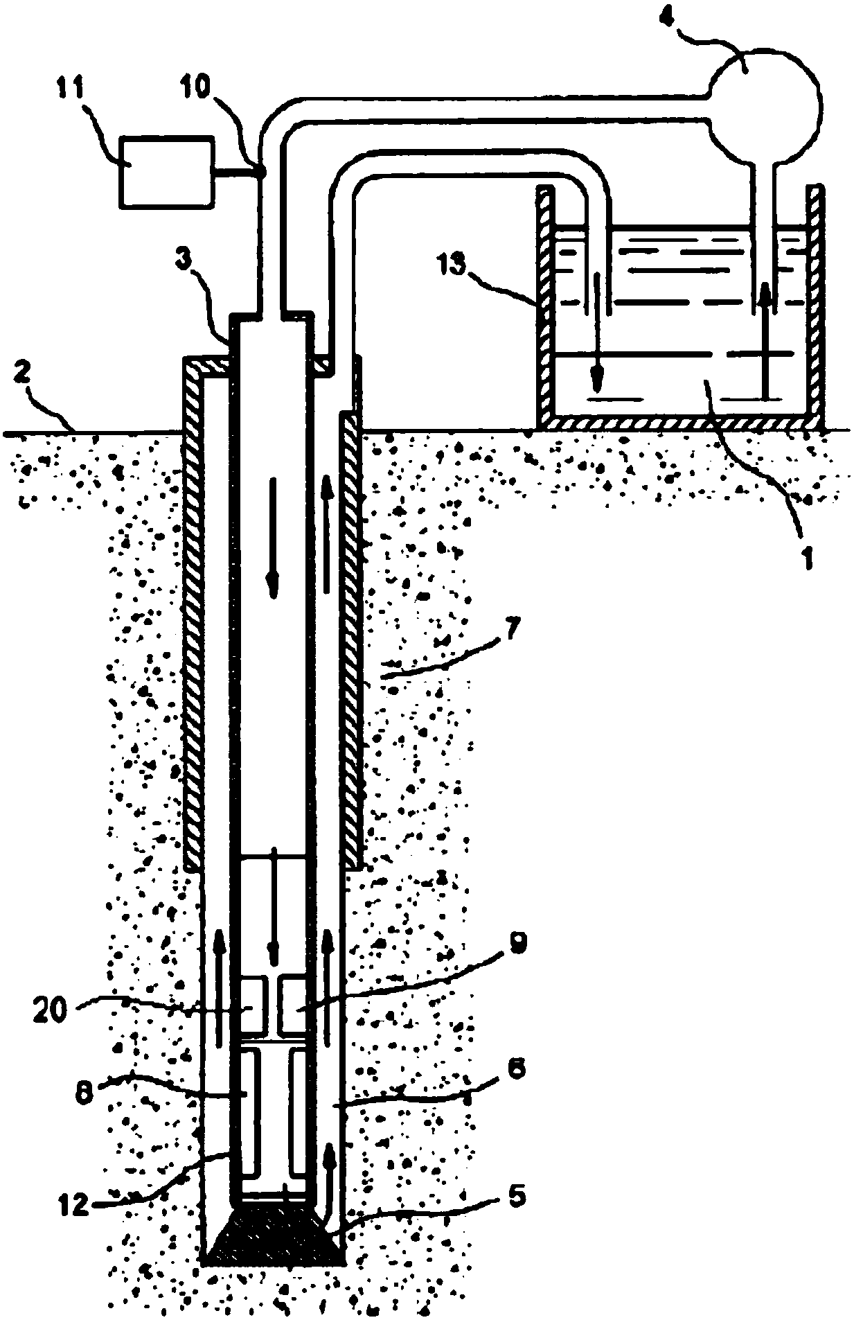
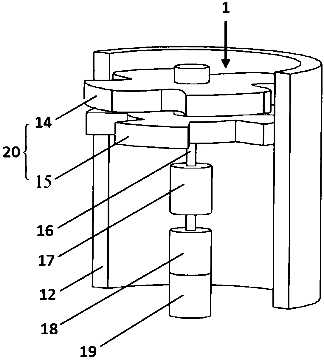
[0019] The rotational speed control method of the rotary valve involved in this embodiment is used to control the rotational speed of the rotary valve rotor in the drilling fluid continuous pressure wave signal generator in the measurement-while-drilling tool in the drilling device, and realizes the control process in the drilling device with the rotary valve installed, The main structure of its drilling equipment includes drilling fluid 1, ground surface 2, drill string 3, drilling fluid pump 4, drill bit 5, annular space 6, formation 7, drilling parameter and formation parameter measurement device 8, drilling fluid continuous pressure wave signal generator 9. Pressure sensor 10, signal processing device 11, drill collar 12 and drilling fluid tank 13; wherein the drilling fluid continuous pressure wave signal generator 9 includes a rotary valve stator 14, a rotary valve rotor 15, a rotor shaft 16, a speed reducer 17, Motor 18, motor control circuit 19 and rotary valve 20; firs...

Embodiment 2

[0023] This embodiment is based on the following calculations and analysis to realize the control of the rotational speed of the rotary valve:

[0024] (1) Realize the linearization correction of the rotary valve speed control system based on feedforward compensation According to the derivative relationship between the speed and the rotation angle, there is If the rotation angle of the rotary valve is controllable, its speed is controllable;

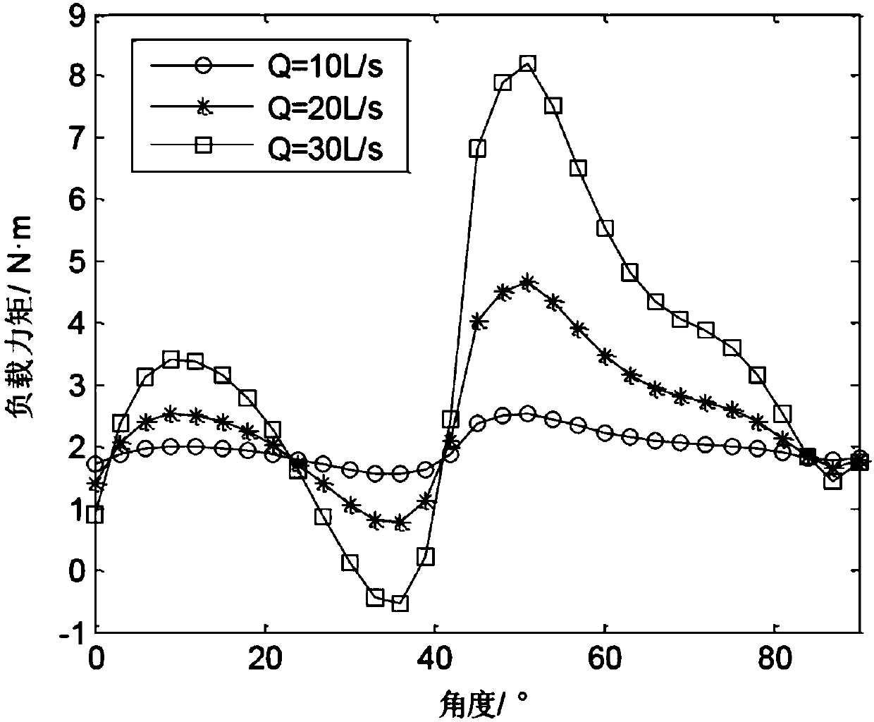
[0025] Load moment M L (θ) is non-monotonic and severely nonlinear with the rotation angle, see the attached image 3 , if the M L The mathematical model of (θ) is expressed in polynomial form

[0026] m mod (θ)=a+ρQ 2 (b 0 +b 1 θ+b 3 θ 2 +Λ+b m θ m ) (1)

[0027] Among them, θ is the rotation angle; Q is the drilling fluid flow rate; ρ is the drilling fluid density; a is a constant; b 0 —b m is the polynomial coefficient; m is the power of each item in the polynomial;

[0028] According to the torque balance equation of ...

Embodiment 3

[0084] In this embodiment, in the drilling device containing the rotary valve in embodiment 1 and based on the principle of embodiment 2, the technological process for realizing the speed control of the rotary valve is as follows:

[0085] First, the feed-forward compensation method is used to correct the nonlinearity of the rotary valve speed open-loop control system, and then the speed open-loop control system that has been linearized and corrected is formed into a PID closed-loop control through negative feedback of the speed, and then the PID parameters are reasonably determined to realize the rotation. Fast follow-up control of the valve speed; in the nonlinear correction process, the angle control item in the angle control mathematical model (2) of the rotary valve is set as a constant, and the motor control voltage expression under ideal conditions expressed by formula (6) is obtained formula, the load torque item in formula (6) is replaced by the mathematical model of r...


PUM


Abstract

The invention relates to a rotating valve rotational speed control method for a measuring-while-drilling tool, and belongs to the technical field of drilling equipment control. A drilling fluid continuous pressure wave signal generator used for measuring while-drilling keeps the rotating valve rotational speed stable and fast adjusting of the rotational speed under the influence of the loading moment of the rotating valve, linearization correction of a rotating valve rotational speed control system is conducted based on feed forward compensation, and linearization correction of a rotating valve rotational speed loop opening control system is achieved; then fast follow control of the rotating valve rotational speed is realized based on PID parameters preferably, fast following of the rotating valve rotational speed on a phase modulation control pulse is realized, the high anti-interference ability and changes of rotating speed fast following phase control pulse are achieved, and fast follow control of the rotating valve rotating speed is achieved; and a rotating valve produces high-quality drilling fluid continuous pressure wave signals, and the requirement of data transmission of measuring while-drilling and logging while-drilling is met. According to the rotating valve rotational speed control method, the control principle is scientific, the control process is simple, the control route is reliable, control equipment is easy to get, and the application environment is friendly.

Description

Technical field: [0001] The invention belongs to the technical field of drilling equipment control, and relates to a method for controlling the rotational speed of a rotary valve of a measurement-while-drilling tool in the process of oil and gas drilling, in particular to a rotary valve used for a drilling fluid continuous pressure wave signal generator in a measurement-while-drilling tool speed control method. Background technique: [0002] Downhole Measurement While Drilling / Logging While Drilling (MWD / LWD) is a modern drilling auxiliary technology that measures and transmits downhole information in real time during drilling. During the drilling process, the drilling fluid is pumped downhole from the surface through the drill string, sprayed out from the water hole of the drill bit for the lubrication and cooling of the drill bit, and returns upward to the wellhead through the annular space between the well wall and the drill string. MWD / LWD tools are installed Inside the...

Claims


Application Information

Patent Timeline
Patent Type & Authority Applications(China)
IPC IPC(8): E21B47/20
CPCE21B47/20
Inventor 沈跃尹笛
Owner CHINA UNIV OF PETROLEUM (EAST CHINA)
Learn More