Centrifugal gas way type gas purifier

A gas purification and airway-type technology, applied in the field of centrifugal airway gas purifiers, can solve the problems of low capture rate, low efficiency, and rapid drop in airflow rotation speed, and achieve the effect of efficiently purifying gas and improving sedimentation efficiency

Active Publication Date: 2016-07-20
翁跃勤
View PDF7 Cites 7 Cited by
  • Summary
  • Abstract
  • Description
  • Claims
  • Application Information

AI Technical Summary

Problems solved by technology

[0002] In people's production and life, there are many occasions that need to purify the air, industrial waste gas or dirty gas. The existing air purification technologies mainly include mechanical filtration, electrostatic dust collection, activated carbon adsorption and other technologies, which have high cost and secondary Pollution, low efficiency and other issues
The existing industrial waste gas or dirty gas purification treatment technologies mainly include mechanical filtration, swirl water film dust removal, water mist dust reduction and other technologies. There is a problem of high cost in purifying industrial waste gas or dirt

Method used


Image

  • Centrifugal gas way type gas purifier
  • Centrifugal gas way type gas purifier
  • Centrifugal gas way type gas purifier

Examples


Embodiment 1

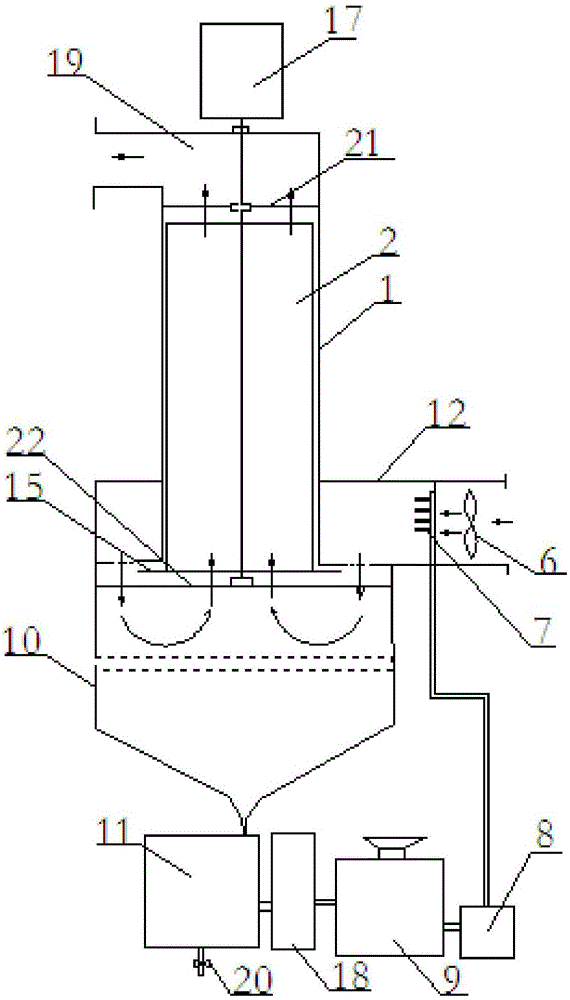
[0056] Such as figure 1 As shown, a centrifugal airway type gas purifier includes an aerosol mixing device, a casing 1, a centrifugal rotor 2 and a power unit, the aerosol mixing device is used to mix gas and water mist, and the casing A centrifugal rotor 2 for absorbing suspended particles in the gas is installed inside. The centrifugal rotor 2 is provided with several centrifugal air passages 4 for airflow to flow through. The power device includes a motor 17, and the motor 17 is in the position of Outside the casing 1, the output shaft of the motor 17 is connected to the rotating shaft of the centrifugal rotor 2 through a coupling.

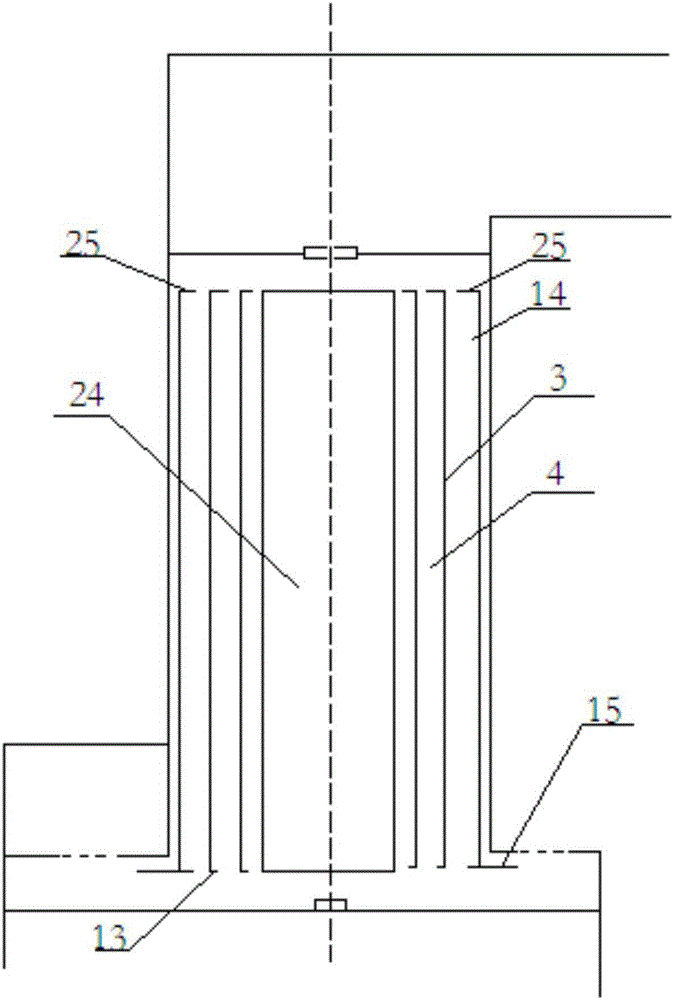
[0057] The air inlet of the centrifugal rotor 2 is connected with the air outlet of the aerosol mixing device, and the air outlet of the centrifugal rotor 2 is connected with the air outlet of the casing 1 . The centrifugal rotor 2 includes several cylinders 3 with unequal diameters that are coaxially fitted together, and the cylinders 3 are c...

Embodiment 2

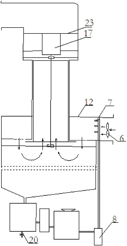
[0069] Such as figure 2 , is the structural representation of embodiment 2. The structure of the second embodiment is basically the same as that of the first embodiment, the only difference lies in the installation position of the motor 17 . The motor 17 is installed outside the casing 1 in Embodiment 1, and the motor is installed in the casing 1 in Embodiment 2. A motor mounting bracket 23 is provided in the air outlet section 19 of the casing 1 , and the motor 17 is mounted on the motor mounting bracket 23 . Adopting the installation method of the motor 17 in Embodiment 2 makes the structure of the product more compact.

[0070] The power device can be an electric motor 17, and other power devices can also be selected, as long as it can provide power to drive the centrifugal rotor 2 to rotate.

[0071] Those skilled in the art can also design the shapes and placement directions of various centrifugal rotors 2 according to the technical features of the present invention, ...


PUM


Abstract

The invention relates to a centrifugal gas way type gas purifier which comprises a gas and spray mixing device, a purifier shell, a centrifugal rotor and a power device. The gas and spray mixing device is used for mixing gas with spray, the centrifugal rotor used for adsorbing suspended particles in the gas is mounted in the purifier shell, a plurality of centrifugal gas ways for gas flow to flow unidirectionally are arranged in the centrifugal rotor, the power device is in transmission connection with the centrifugal rotor to drive the same to rotate, and a gas inlet of the centrifugal rotor is connected with a gas outlet of the gas and spray mixing device. The gas and spray mixing device mixes the gas with the spray and provides power to feed mixed gas to the centrifugal gas ways, the centrifugal rotor driven by the power device rotates at a high speed, and the suspended particles in the mixed gas entering the centrifugal gas ways are adhered on the inner walls of the centrifugal gas ways under action of centrifugal force, so that the suspended particles and harmful gas in the gas are removed circularly to achieve the objective of efficiently purifying the gas.

Description

technical field [0001] The invention relates to a purification device, in particular to a centrifugal airway type gas purifier for gas purification. Background technique [0002] In people's production and life, there are many occasions that need to purify the air, industrial waste gas or dirty gas. The existing air purification technologies mainly include mechanical filtration, electrostatic dust collection, activated carbon adsorption and other technologies, which have high cost and secondary Pollution, low efficiency and other issues. The existing industrial waste gas or dirty gas purification treatment technologies mainly include mechanical filtration, swirl water film dust removal, water mist dust reduction and other technologies. There is a problem of high cost in purifying industrial waste gas or dirty gas with mechanical filtration technology. Using swirl water film dust removal technology Purification and treatment of industrial waste gas or dirty gas has problems ...

Claims


Application Information

Patent Timeline
IPC IPC(8): B01D50/00B01D45/12B01D53/18C02F9/04
CPCB01D45/12B01D53/18C02F9/00C02F1/00C02F1/001C02F1/52C02F1/50C02F2301/08B01D50/10B01D50/40
Inventor 翁跃勤
Owner 翁跃勤
Why Eureka
Try Eureka