This helps you quickly interpret patents by identifying the three key elements:
Problems solved by technology
Method used
Benefits of technology
Benefits of technology
[0009]The present invention aims to provide a heat accumulation element efficiently storing heat of exhaust gas or the like, being capable of being effectively used, and being excellent in durability.
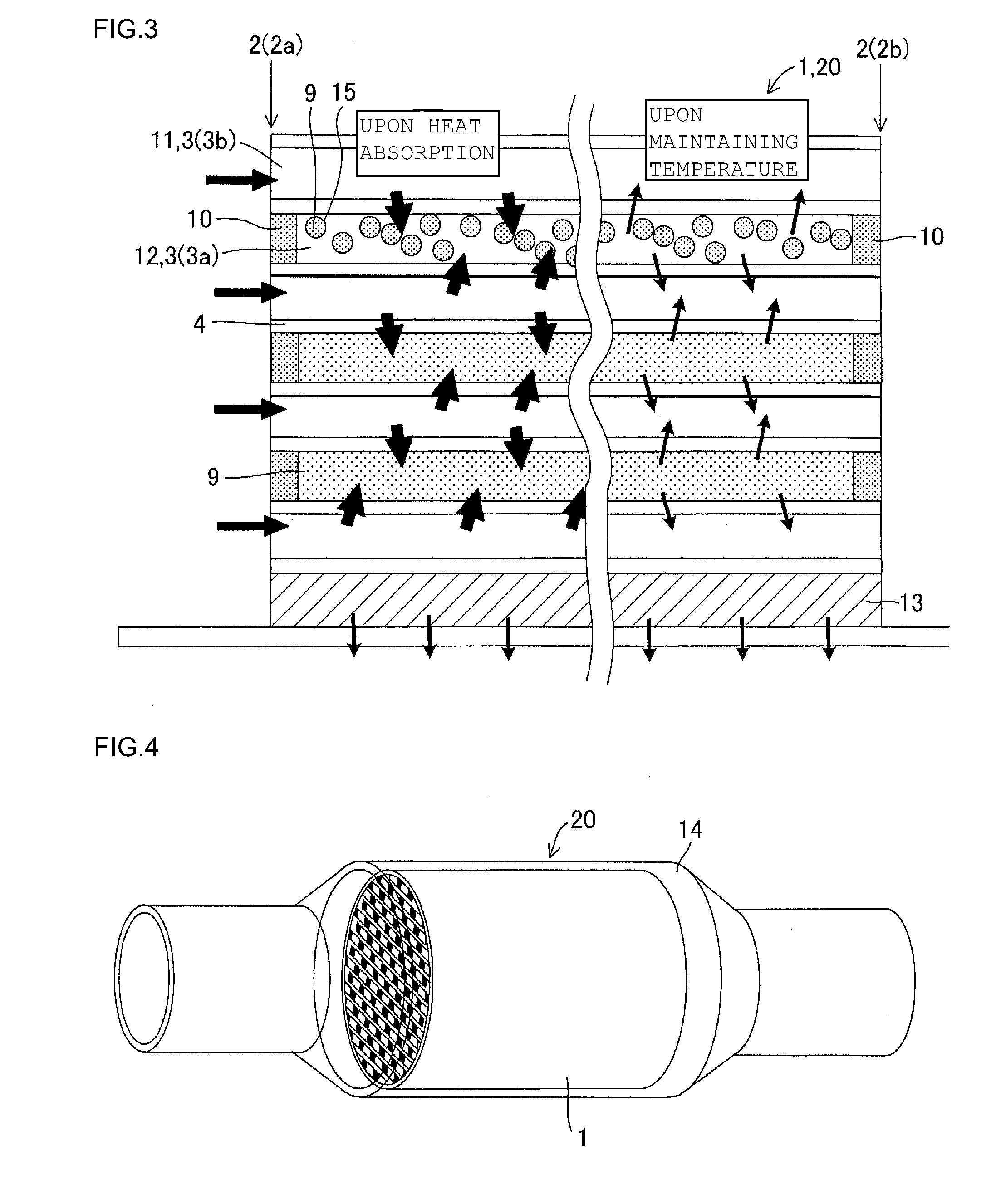
[0019]In a heat accumulation element of the present invention, heat of a heat carrier such as exhaust gas is efficiently stored and effectively used. For example, in the case that it is used as a catalyst converter, catalyst activation time upon restart of engine can be shortened to be able to efficiently purify exhaust gas.
Problems solved by technology
However, in JP-A-6-254403, JP-W-2002-514707 and JP-W-2003-521627, heat is not efficiently stored or effectively used.
In particular, in the case that a heat accumulation element described in JP-A-6-254403, JP-W-2002-514707 and JP-W-2003-521627 is used in automobile exhaust gas, since the material is metal, there arises a problem of easy corrosion by a sulfur component contained in exhaust gas.
In addition, a heat accumulation type heat exchanger of JP-A-11-264683 has an installation limitation since the direction of flow passages is limited to a vertical direction.
Further, since the bottom ends of the flow passages where the phase-changing substance is filled are merely fixed with a ceramic filler using a ceramic bonding material, the phase-changing substance may leak out from the bottom ends.
Therefore, there is a high possibility of leakage of the phase-changing substance from the heat storage typeheat exchanger by vibrations in the case of mounting it on an object having vibrations, such as an automobile.
However, in this structure, though heat from the fluid can easily be stored on the side where it is brought into contact with partition walls of the phase-changing substance, heat cannot be stored on the side where the fluid is brought into contact with partition walls.
Therefore, it does not store heat efficiently as a whole.
Method used
Image
Click on the blue label to locate the original text in one second.
Reading with bidirectional positioning of images and text.
Examples
example
[0058]Hereinbelow, the present invention will be described in more detail on the basis of Examples. However, the present invention is by no means limited to these Examples.
[0059]A catalyst converter with a heat accumulating function was manufactured, and FTP performance and the presence / absence of leakage of the heat accumulating medium were checked.
[0060](Manufacture of Main Body of Heat Accumulation Element (Material: Cordierite))
[0061]Cordierite was employed as the raw material and subjected to extrusion forming using a metallic die, and one side was plugged with cordierite, which was the same material as for the honeycomb structure, followed by firing. At that time, as shown in FIG. 8, the open cells 3b had a quadrangular cross-sectional shape with the vertex angles 3k having curvature. As the size after firing, the length in the exhaust gas flow direction was 100 mm, the diameter of the end face was 100 mm, the cell density was 80 cells / cm2, and the partition wall thickness was...
examples 1 , 2 and 5
Examples 1, 2 and 5, and Comparative Examples 3 and 4
[0075]Since Comparative Example 3 had a small density of 0.5 g / cm3, the honeycomb structure itself became porous, which seems to have served as a cause of leakage of the heat accumulating medium. On the other hand, Comparative Example 4, though it had a high density of 4.5 g / cm3, had thermal shock reduction of exhaust gas, and crack generation was recognized in the honeycomb structure in addition to leakage of the heat accumulating medium. Therefore, the density is larger than 0.5 g / cm3, preferably below 4.5 g / cm3, more preferably 1.0 to 4.0 g / cm3.
[0076]From the results of Examples 2, 3 and 4, and Comparative Example 5, the enclosurevolume fraction of the heat accumulating medium is preferably below 100%. The heat storage medium may have volume expansion upon storing heat, and, by forming a space, the volume expansion is considered to be relaxed. This seems to be the cause of no leakage of the heat accumulating medium from the honeycomb structure in the case of the enclosurevolume fraction of below 100% of the heat accumulating medium. However, in order to enhance heat accumulating effect as a heat accumulation element, the heat accumulating medium enclosure volume fracture is preferably 70 to 90%.
(5) Comparison of Form of the Heat Accumulating Medium
PUM
Property
Measurement
Unit
Fraction
aaaaa
aaaaa
Fraction
aaaaa
aaaaa
Density
aaaaa
aaaaa
Abstract
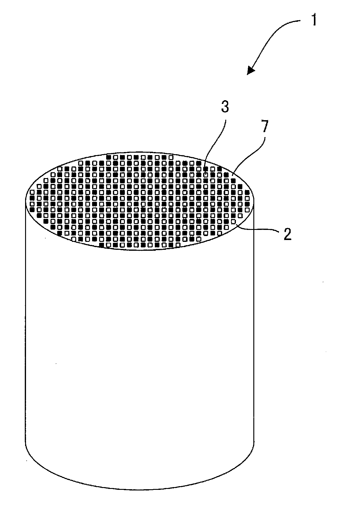
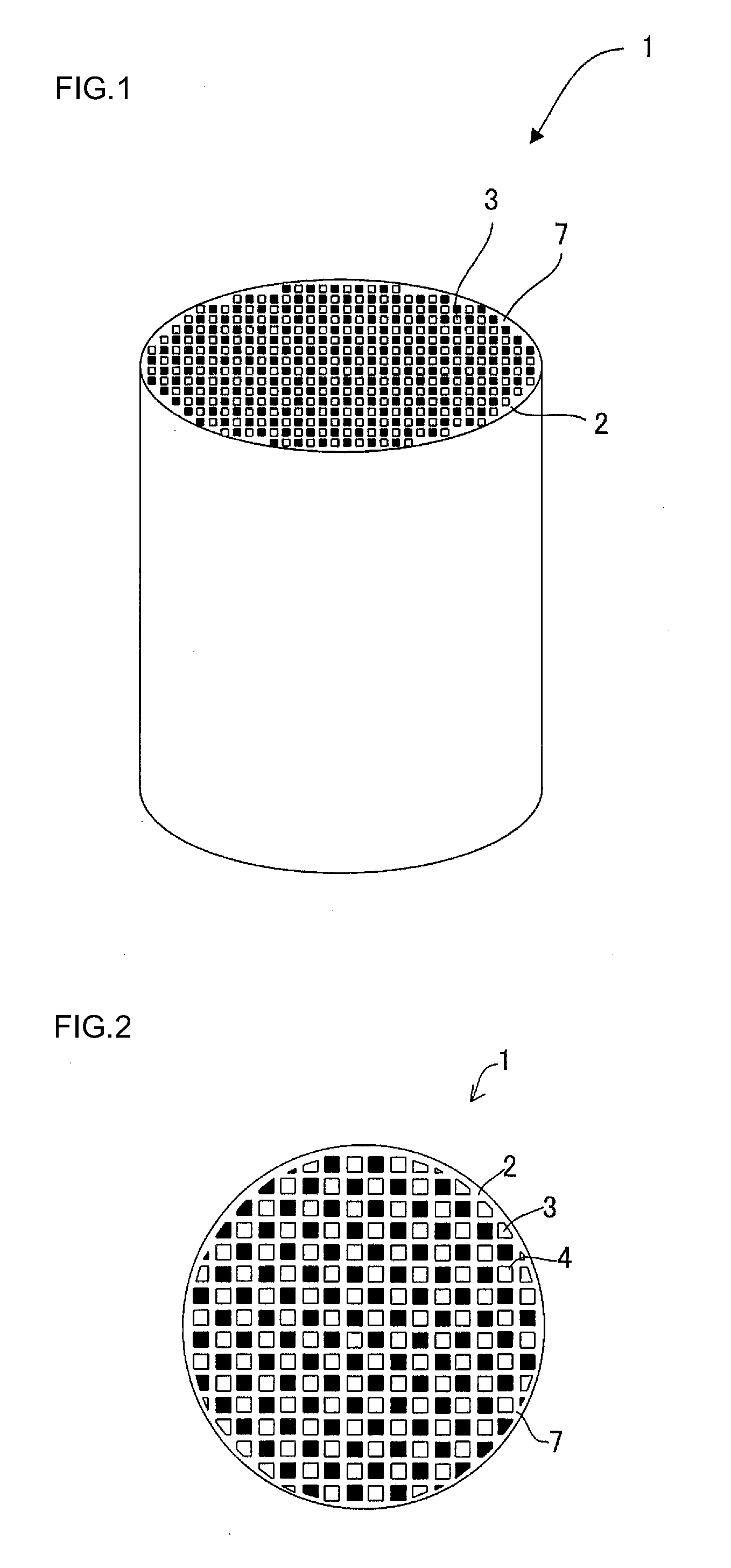
The main body of the heat accumulation element has a honeycomb structure, and fluid passages where a fluid circulates and heat accumulating medium portions where a medium for storing heat is enclosed are formed. Specifically, the heat accumulation element has partition walls, and one opening portion and the other opening portion of each of the predetermined cells of a honeycomb structure having a large number of cells partitioned and formed to function as fluid passages are plugged and fired to form plugged cells. A heat accumulating medium is provided in the plugged cells. Open cells neither plugged nor fired serve as fluid passages with the plugged cells plugged and fired serving as heat accumulating medium portions, and the fluid circulating through the open cells and the heat accumulating medium in the plugged cells exchange heat.
Description
BACKGROUND OF THE INVENTION AND RELATED ART STATEMENT[0001]The present invention relates to a heat accumulation element which efficiently stores heat of a heat carrier such as exhaust gas, effectively uses the heat, and is excellent in durability.[0002]Generally, running energy of an automobile is merely about 25% of fuel combustion energy. The rest becomes an energy loss such as s cooling loss (engine cooling water of 30%) and an exhaust gas loss (exhaust gas of 30%). From 2010, CO2 reduction is severe in the automobile field, and gasoline mileage is strengthened. Therefore, many automobile companies are working on reduction in exhaust gas loss, for example, exhaust heatrecovery technology as a measure for reducing an energy loss for improving automobile gasoline mileage.[0003]JP-A-6-254403 discloses an exhaust gas purification catalyst capable of improving exhaust gas purification performance on start-up by shortening the time until the catalyst activity on engine start-up from t...
Claims
Application Information
Patent Timeline
Application Date:The date an application was filed.
Publication Date:The date a patent or application was officially published.
First Publication Date:The earliest publication date of a patent with the same application number.
Issue Date:Publication date of the patent grant document.
PCT Entry Date:The Entry date of PCT National Phase.
Estimated Expiry Date:The statutory expiry date of a patent right according to the Patent Law, and it is the longest term of protection that the patent right can achieve without the termination of the patent right due to other reasons(Term extension factor has been taken into account ).
Invalid Date:Actual expiry date is based on effective date or publication date of legal transaction data of invalid patent.

