Method for handling material in a material conveying system, a separating device arrangement and a material conveying system

Active Publication Date: 2021-12-16
MARICAP OY
View PDF0 Cites 1 Cited by
  • Summary
  • Abstract
  • Description
  • Claims
  • Application Information

AI Technical Summary

Benefits of technology

[0013]The solution according to the invention has a number of important advantages. By means of the invention the drawbacks of prior-art solutions can be avoided.
[0014]By using a separating device arrangement according to one embodiment of the invention, the separation of material particles from the conveying air in the standby separating device can be improved. It is thereby possible to significantly improve the prevention of the material to be separated from displacing along with the conveying air via the standby separating device of the separating device arrangement towards the output channel leading to the suction side of the partial-vacuum source. In this case, e.g. waste particles, such as papers or plastic films or bags, can be more effectively made to remain in the separating devices of the separating device arrangement. Thus, an operationally reliable separating device arrangement for a pneumatic waste conveying system can be achieved. In the separating device of the separating device arrangement according to one embodiment of the invention, the flow of conveying air in the chamber space of the separating device or in the output channel can be acted upon by bringing about a guiding effect for the conveying air in the opposite direction with respect to its direction of rotation. With this, it is further possible to significantly improve prevention of the material to be separated from displacing along with the conveying air from the container space of the separating device towards the output channel. In this case, e.g. waste particles, such as papers or plastic films or bags, do not easily get into the output aperture of the separating device and/or block the output aperture, and an operationally reliable separating device for use in the separating device arrangement can be achieved. The desired effect can be brought about by arranging an output branch in the wall of the output channel in such a way that a flow of the conveying air from the output channel into the output branch is brought about in a mainly tangential direction with respect to the wall of the output channel. This can be achieved e.g. by arranging the output branch eccentrically in the output channel. The separating device arrangement according to the invention is suited both to material conveying systems in which a formatter, i.e. a rotary shaper, is used to compact and/or shape the material to be conducted into the conveying piping from the input points, and to ordinary pneumatic pipe conveying systems for material wherein material is fed in from an input point directly into the conveying piping. By using a deep collection container as a separating device, the material conveyed into the collection container can be efficiently stored, and emptying of the container can be performed less frequently. Emptying of the collection container can be performed by lifting the collection container, and by transferring the material that has collected in the container from an openable and closable aperture arranged in the bottom part of the container into the container of a transportation means, such as of a garbage truck. The transportation means can comprise a press for compressing the material so it becomes denser and a hoist for lifting the collection container. With the solution according to the invention, the separating device of a pneumatic pipe conveying system for material and the collection container intended for temporary storage of the material conveyed can be efficiently combined. When the collection container is a so-called deep collection container, which is at least partly em

Problems solved by technology

In pneumatic material conveying systems, in which e.g. household waste or recycleable material is conveyed, one problem sometimes is that material particles that are light in weight but large in surface area, such as loose papers or plastic, are not necessarily separated from th

Method used


Image

  • Method for handling material in a material conveying system, a separating device arrangement and a material conveying system
  • Method for handling material in a material conveying system, a separating device arrangement and a material conveying system
  • Method for handling material in a material conveying system, a separating device arrangement and a material conveying system

Examples


Example

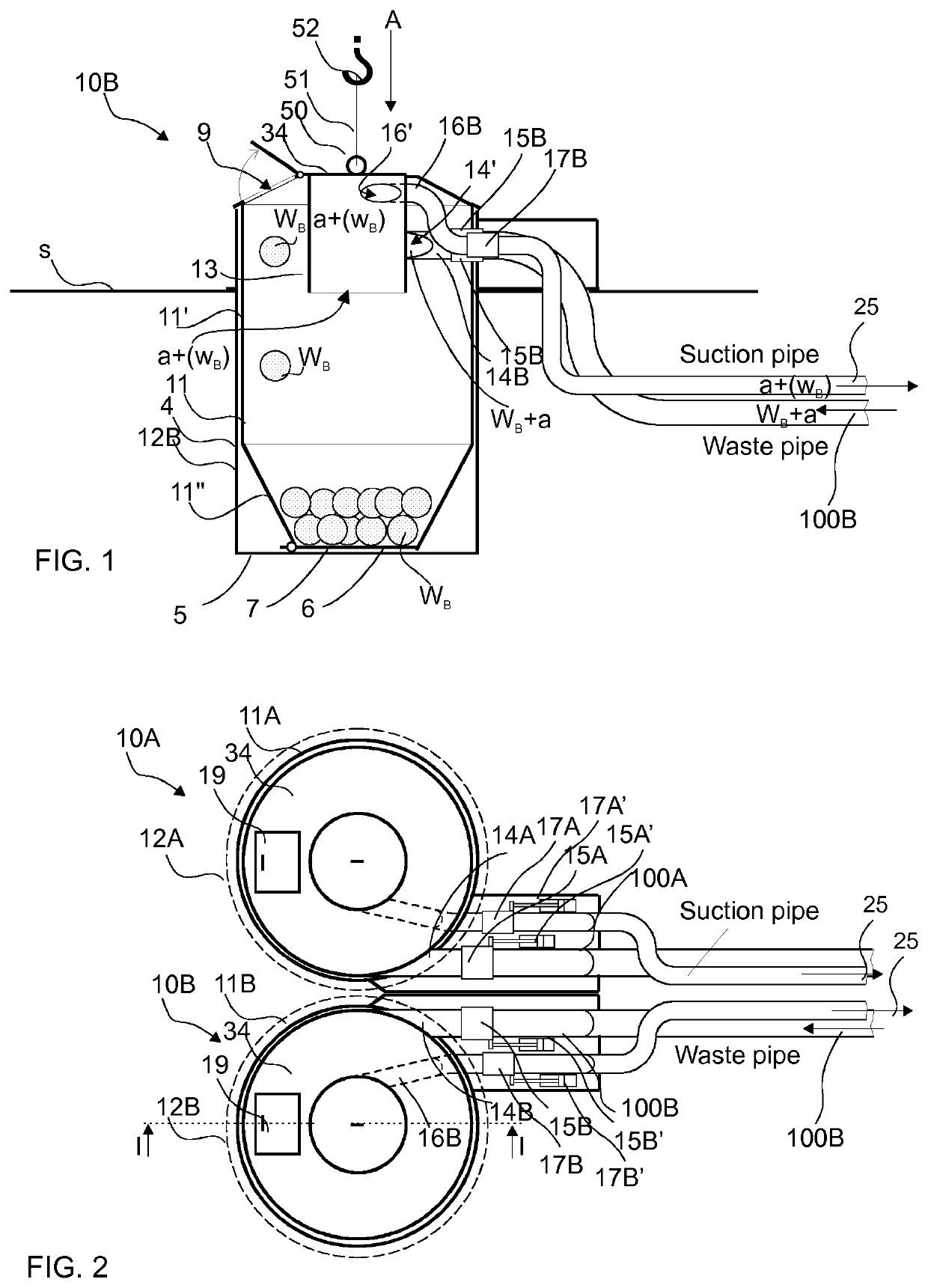
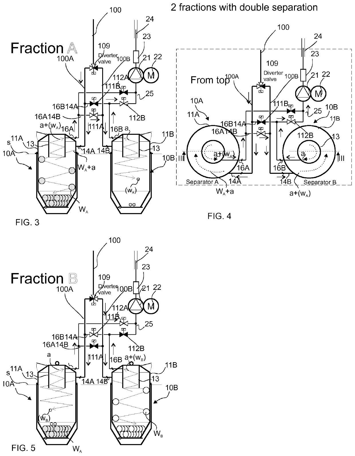
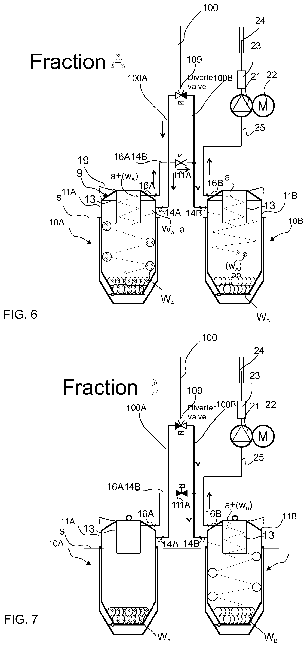
[0028]In the figures, a form of presentation has been used for the valves wherein an open pathway through a valve is presented with a white marking for the valve, and a closed pathway with a black marking for the valve. In addition, in a figure the diagrammatic directions of movement of conveying air a and / or materials in different operating states are presented with arrows. In the text, the term ‘pipe’, ‘channel’ or ‘branch’ can mean generally a material pathway, or a part thereof, and / or a conveying air pathway, or a part thereof. A pathway can typically be e.g. a pipe or hose.

[0029]In the following, the operation of one separating device is first presented at a general level with the aid of FIG. 1, which presents one partially-sectioned separating device 10B of a pneumatic material conveying system. The separating device 10B is operatively adapted to be connected to a material conveying pipe 100B of a pneumatic material conveying system, via which pipe the material WB is conducte...


PUM


Abstract

A method for handling material and conveying air in a pneumatic conveying system for material, which conveying system comprises at least one input point (1) for material, a material conveying pipe (100), which is connectable to an input point (1), and at least two separating devices (10A, 10B), in which the material being conveyed is separated from the conveying air, and also means for bringing about a pressure difference and/or a transporting air flow in the conveying pipe (100) at least during the conveyance of material, which means comprise at least one partial-vacuum source (21). In the method, material is conveyed in a transporting air flow in a material conveying pipe from an input point in a selected manner into one of at least two separating devices (10A, 10B), and that at least one of the aforementioned separating devices (10A, 10B) is configured to function as the standby separating device of a second separating device. The object of the invention is also a separating device arrangement and a waste conveying system.

Description

BACKGROUND OF THE INVENTION[0001]The object of the invention is a method as defined in the preamble of claim 1.[0002]The object of the invention is also a separating device, as defined in claim 21, for a material conveying system.[0003]The object of the invention is also a waste conveying system as defined in claim 36.[0004]The invention relates generally to pneumatic material conveying systems, such as to partial-vacuum conveying systems, more particularly to the collection and conveying of waste material or recycleable material, such as to the conveying of household wastes.[0005]Systems wherein wastes are conveyed in piping by means of suction and / or conveying air are known in the art. In these systems, wastes are moved long distances in the piping pneumatically, by means of suction and / or a pressure difference, together with the conveying air. The apparatuses are used for, inter alia, the conveying of wastes in different institutions, for the conveying of household waste, or for ...

Claims


Application Information

Patent Timeline
IPC IPC(8): B65F5/00B65F1/10B65G53/60B65G53/52B01D46/00
CPCB65F5/005B65G53/52B65G53/60B65F1/105B04C5/28B04C11/00B65G53/34B65G43/00
Inventor SUNDHOLM, GÖRAN
Owner MARICAP OY
Why Eureka
Try Eureka