
Contaminant extraction systems, methods and apparatuses

Inactive Publication Date: 2006-08-24
SENTOR TECH
View PDF17 Cites 36 Cited by
  • Summary
  • Abstract
  • Description
  • Claims
  • Application Information

AI Technical Summary

Benefits of technology

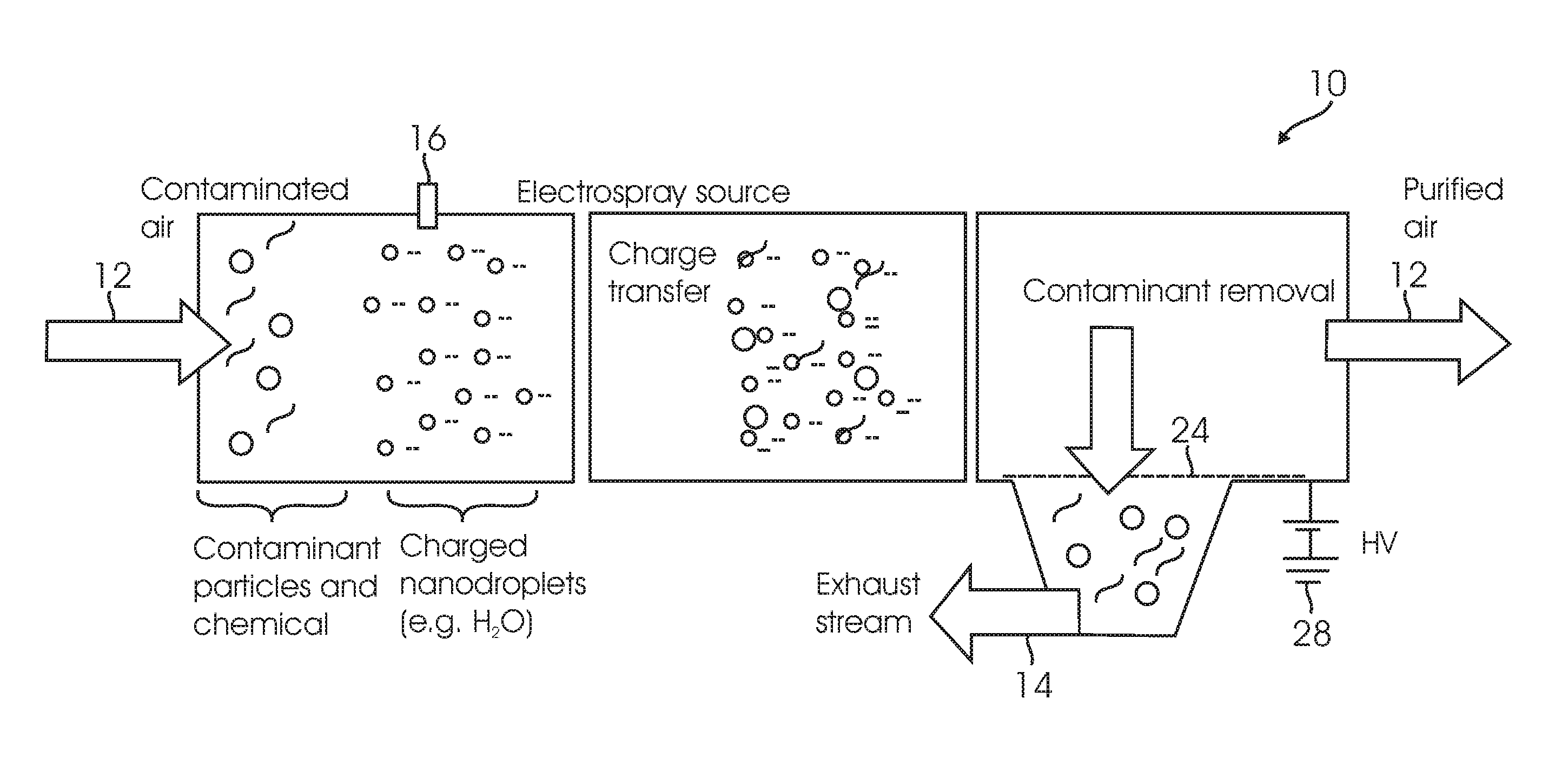
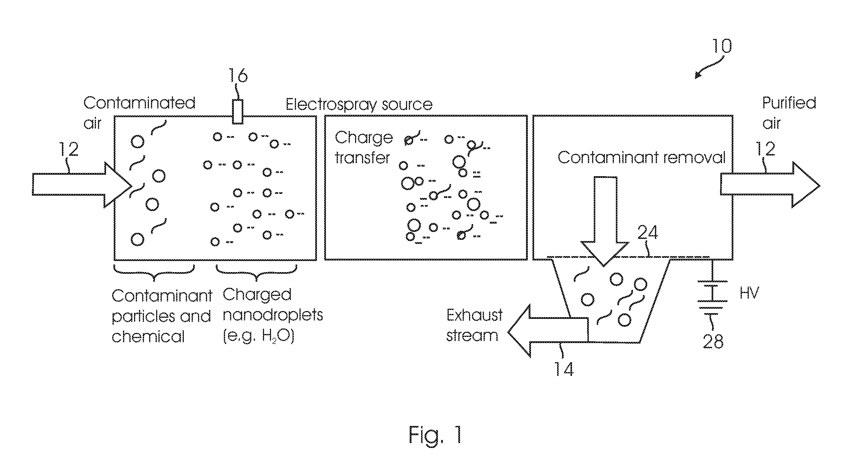
[0018] Another aspect of the embodiments is that the charged droplets may change from the liquid phase to the vapor phase before they encounter or reach the extraction grid. This can help retain solvent in embodiments which require the replenishment of amounts of solvent or they assist with solvent recirculation.
[0021] Another aspect of the embodiments is that the airflow rate and charged droplet delivery rate may be correlated for greater or maximum efficiency. This correlation can be accomplished, for example, by varying the number of emitters so that the number of emitters used determines the maximum amount (in cfm) of air that can be efficiently purified.

Problems solved by technology

In use, known air filters used for personal protection and air purification do not allow for sufficient air circulation and heat stress is a significant issue that affects the health, safety, and operational performance of the Soldier, Marine, Sailor, Airman, and Emergency Responder.
One issue is the prior art's inability to reject metabolic body heat to the environment due to the insulation characteristics of their personal protective clothing.
As a result, body heat is stored, core temperature rises and operational performance can become severely impaired.
They are not universally effective at removing various classifications of contaminants (e.g. bacterial spores versus chemicals).
Finally, they are bulky and costly, requiring large blowers and the filters are consumables and, once used, must be disposed of as hazardous waste.

Method used


Image

  • Contaminant extraction systems, methods and apparatuses
  • Contaminant extraction systems, methods and apparatuses
  • Contaminant extraction systems, methods and apparatuses

Examples


Embodiment Construction

[0046] In describing multiple embodiments of the claimed subject matter, including those embodiments illustrated in the drawings, specific terminology is employed for the sake of clarity. Although these parameters will now be discussed in further detail, these descriptions are not an exhaustive explanation of all possible variations in structure and operation. It will be apparent to those skilled in the art that various other changes or modifications can be made without departing from the spirit and scope of the embodiments presented herein. It should be further apparent that any or all combinations of the individual described variations with the disclosed embodiments are possible. Therefore, the scope of the claimed subject matter is defined by the appended claims and their equivalents.

[0047] Embodiments of the systems, methods, and apparatuses have thus far been described without reference to specific elements which may be suitable for operation. Also, as used herein, the article...


PUM


Abstract

A contaminant extraction apparatus, systems and method for extracting contaminants, such as particles and polar molecules, from an air flow containing a contaminated gas such as air so that the contaminants are expelled from the embodiments after they are extracted. One method includes the steps of generating two electric fields in separate air flow channels separated by an extraction grid with the second electric field having a greater potential difference than the first electric field; generating a first air flow through the first air flow channel and a second air flow through a second air flow channel; dispensing charged liquid droplets into the first air flow using at least one charged droplet generator; allowing the droplets to transfer charge to those contaminants; and expelling the contaminants into the second air flow using the potential difference in the second electric field.

Description

BACKGROUND [0001] A. Field of the Invention [0002] Embodiments of the claimed subject matter relate to methods, systems and apparatuses for purifying air, and more particularly, to systems, methods and apparatuses for removing particles and contaminants from an air flow by attracting the particles and contaminants to charged spray droplets of a fluid introduced to the air flow. [0003] B. Description of Related Art [0004] The technique of electrospray ionization is well described and known to those skilled in the art. Prior art air purification apparatuses and methods include U.S. Pat. No. RE 30,479 to Cohen, et al. which illustrates a method for the removal of particulate matter as well as noxious gases and vapors from a gas stream. This is accomplished by means of charged droplets having a size between 60 and 250 microns and preferably between 80 and 120 microns. The droplets are generated by first ejecting a stable jet of liquid such as water and the liquid jet is broken up into c...

Claims


Application Information

Patent Timeline
IPC IPC(8): B03C3/16
CPCB03C3/16B03C2201/32
Inventor TEPPER, GARY C.
Owner SENTOR TECH
Learn More