
Suction retaining device used in water channel field

A technology in the waterway and field, applied in water supply devices, valve devices, spray devices, etc., can solve problems such as inconvenient use, waste of water resources, lower water pressure, etc., and achieve easy assembly, high action accuracy, and strong plugging performance Effect

Active Publication Date: 2011-01-26
XIAMEN SOLEX HIGH TECH IND CO LTD
View PDF4 Cites 4 Cited by
  • Summary
  • Abstract
  • Description
  • Claims
  • Application Information

AI Technical Summary

Problems solved by technology

The existing air suction mechanisms only have the function of air intake, and do not have the function of water blocking or air suction anti-reverse function, so there are the following disadvantages: in the multi-functional shower, when the water outlet function of the shower turns to the non-suction state When the function is switched (such as when it is in the function of non-foaming water outlet), the resistance of the water pipe becomes larger, the water flow will flow backwards, and the water flow will leak out through the suction hole, which will cause inconvenience in use, waste of water resources, and lower water pressure.

Method used


Image

  • Suction retaining device used in water channel field
  • Suction retaining device used in water channel field
  • Suction retaining device used in water channel field

Examples


Embodiment 1

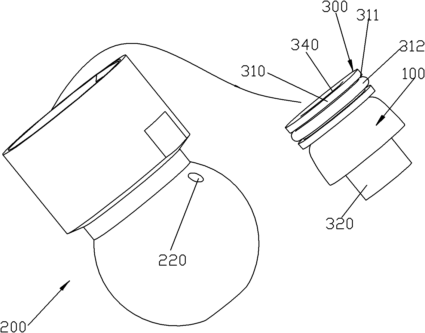
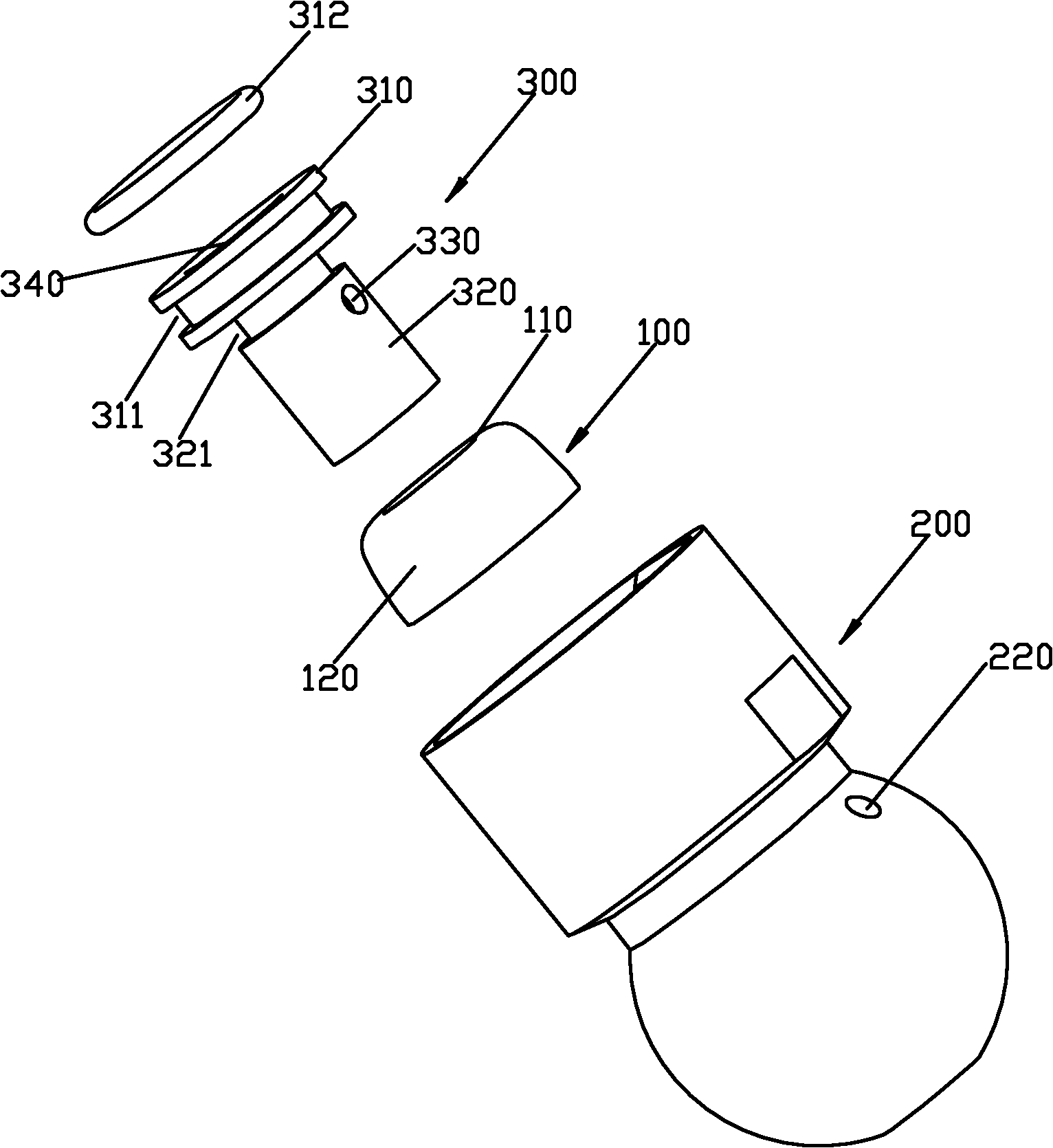
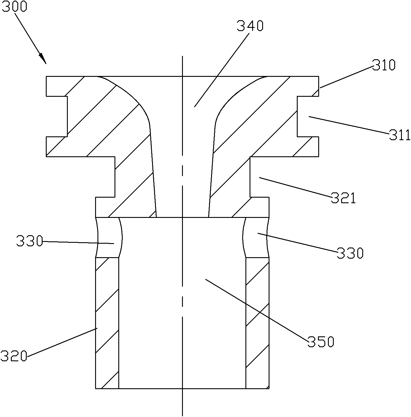
[0042] Please check Figure 1 to Figure 6 , an anti-reverse suction device used in the waterway field, which includes a main body and an elastic sealing sleeve 100 .

[0043] The main body includes a base 200 and an inner frame 300 .

[0044] A stepped hole and two first through holes 220 are defined in the support 200 .

[0045] The stepped hole has a large hole 211 and a small hole 212, and the large hole 211 and the small hole 212 are arranged up and down. In this embodiment, the stepped holes are rotary holes. The upper port of the large hole 211 is provided with an internal thread.

[0046] The two first through holes 220 are arranged symmetrically. The first through hole 220 runs through the inside and outside of the large hole 211, the axis of the first through hole 220 is inclined, the outer port of the first through hole 220 is located on the outer side of the support 200, the first through hole 220 The inner port of is located on the inner side of the large hole...

Embodiment 2

[0055] Please check Figure 7 to Figure 10 The difference between this preferred embodiment 2 and the preferred embodiment 1 lies in that: the outer turning surface of the upper end of the support 200 is provided with external threads; the axis of the first through hole 220 is arranged horizontally.


PUM


Abstract

The invention discloses a suction retaining device used in the water channel field, which comprises a main body and an elastic sealing sleeve, wherein the main body is internally provided with a water channel and at least one air inlet hole; the water channel comprises a water inlet hole and a mutation cavity communicated with the water inlet hole, and the section area of the mutation cavity is greater than that of the water inlet hole; the air inlet hole comprises an air inlet and an air outlet, the air inlet is arranged outside the main body, and the air outlet is arranged in the mutation cavity; the elastic sealing sleeve is sleeved in the main body and fitted with the air inlet hole of the main body; in case the water in the water channel flows clockwise, a negative pressure is produced in the mutation cavity and the mutation cavity adsorbs the elastic sealing sleeve so as to conduct the air inlet hole for inhale; and in case the water channel flows anticlockwise, the hydraulic pressure of the water channel acts on the inner side face of the elastic sealing sleeve so as to enable the elastic sealing sleeve seal the water inlet hole.

Description

technical field [0001] The invention relates to an air suction anti-reverse device used in the field of waterways. Background technique [0002] In the existing waterway field, suction mechanisms are often used, such as bubblers in the waterway field. The existing air suction mechanisms only have the function of air intake, and do not have the function of water blocking or air suction anti-reverse function, so there are the following disadvantages: in the multi-functional shower, when the water outlet function of the shower turns to the non-suction state When the function is switched (for example, when it is in the function of non-foaming water outlet), the resistance of the water pipe becomes larger, the water flow will flow backward, and the water flow will leak out through the suction hole, which will cause disadvantages such as inconvenient use, waste of water resources, and lower water pressure. Contents of the invention [0003] The invention provides an air suction...

Claims


Application Information

Patent Timeline
Patent Type & Authority Applications(China)
IPC IPC(8): E03C1/084F16K15/18B05B12/00
Inventor 江力陈健民陈斌周华松
Owner XIAMEN SOLEX HIGH TECH IND CO LTD
Learn More