Office partitions

A technology of crosspieces and columns, which is applied in the field of office partitions, can solve the problems of long installation period, poor functionality, and high noise, and achieve the effect of short installation period, simple appearance and low noise

Active Publication Date: 2011-01-26
HALUMM CONSTRUCTION TECHNOLOGY CO LTD
View PDF7 Cites 6 Cited by
  • Summary
  • Abstract
  • Description
  • Claims
  • Application Information

AI Technical Summary

Problems solved by technology

[0003] In order to overcome the disadvantages of the prior art that the partition cannot form a whole, the appearance is not simple, the installation period is long, the noise is loud, and the function is not strong, the present invention provides a hidden frame structure, the glass does not contact the column profile, and the partition panel forms As a whole, the appearance is simple and transparent, the installation period is short, the noise is small during the installation process, and the office partition with strong functions

Method used


Image

  • Office partitions
  • Office partitions
  • Office partitions

Examples


Embodiment 1

[0030] refer to Figure 1-5

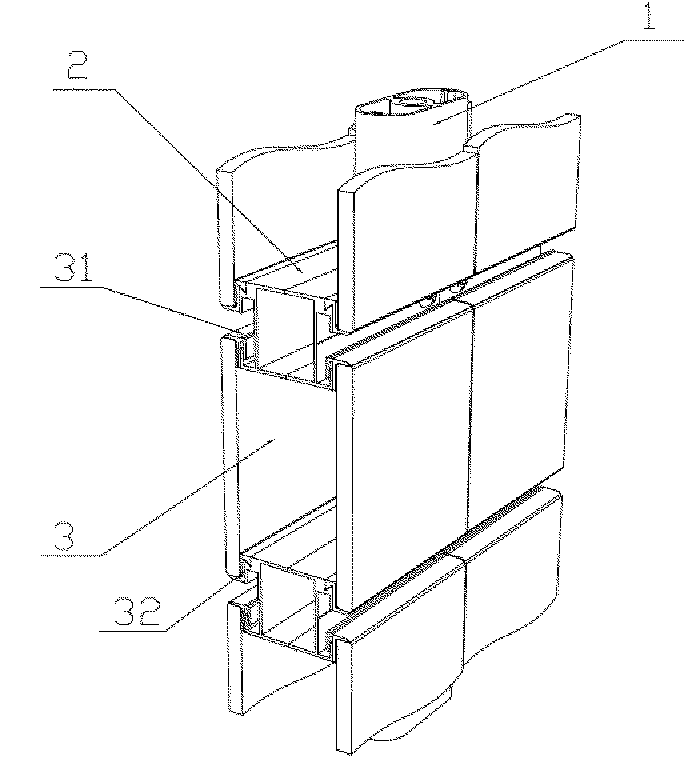
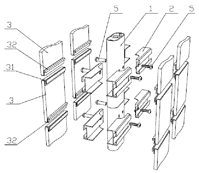
[0031] The office partition is formed by splicing a plurality of partition units. The partition unit includes two partition columns 1 fixed on the ground, a partition rail 2 erected between the two columns and fixed to the column by screws, and hung on the The panel 3 on the crosspiece 2; the partition crosspiece 2 is perpendicular to the partition column 1, and the partition column 1 is provided with a plurality of partition crosspieces 2 along the height direction, and one panel 3 is hooked to two adjacent Partition rung 2 on.

[0032] The partition crosspiece 2 is a cuboid, the top and bottom of the crosspiece 2 are respectively provided with an upper convex strip 21 and a lower convex strip 22, and the lower convex strip 22 is provided with a hooking groove;

[0033] The top and the bottom of the panel 3 are respectively fixed with an upper hanging bar 31 and a lower hanging bar 32 adapted to the width of the panel, and the upper hanging bar...

Embodiment 2

[0042] Refer to attached Figure 6-9

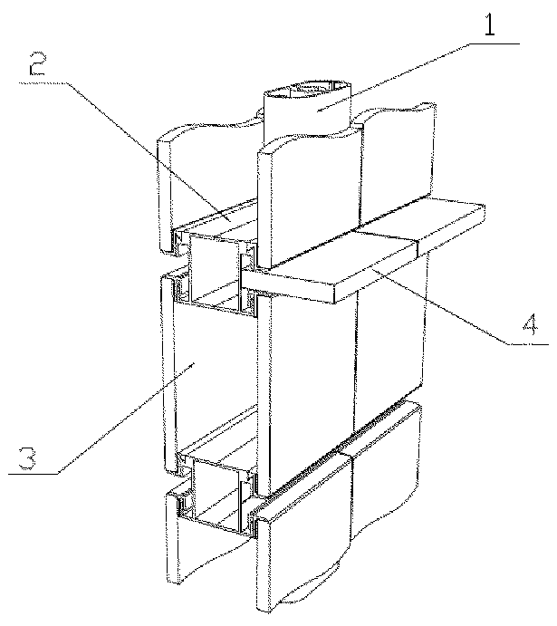
[0043] The difference between this embodiment and the first embodiment is that: the inner surface of the panel 3 is bonded with an iron sheet 6 , and the iron sheet 6 is located between the upper hanging bar 31 and the lower hanging bar 32 .

[0044] A desktop board 7 is erected between the upper convex strip 21 and the lower convex strip 22 of the partition rail 2, and one end of the desktop board 7 passes through a connecting piece 8 that can be embedded in the gap of the partition rail 2 It is fixedly connected with the partition rail 2, and the other end is provided with a supporting leg 71.

[0045] The desktop board 7 is fixedly connected to the partition crosspiece 2 through at least one (generally two) of the connecting pieces 8, and the connecting piece 8 includes screws fixed to the partition crosspiece 2. The connected connecting plate 81, and the supporting plate 82 integral with the connecting plate 81 and perpendicular to ...


PUM


Abstract

The invention discloses office partitions, which consist of a plurality of partition units. Each partition unit comprises two partition upright posts, a partition crosspiece and a panel; the partition crosspiece is vertical to the partition upright posts; the partition upright posts are provided with a plurality of partition crosspieces along the height direction; and the panel is hung on two adjacent partition crosspieces. Each partition crosspiece is provided with an upper rib and a lower rib; a hanging slot is arranged on the lower rib; an upper hanging strip and a lower hanging strip which are matched with the width of the panel are fixed on the panel; the upper hanging strip comprises a fixed strip, a first fin and a second fin; the lower hanging strip comprises a support strip adhered with the bottom of the panel; the side wall of the support strip is adhered with the inner surface of the panel; and the top of the side wall of the support strip bends inwards to form a bending part capable of being lapped on the partition crosspiece on the lower side. The office partitions can be formed into a whole, and have the advantages of simple appearance, short mounting period and small noise during the mounting process.

Description

technical field [0001] The invention relates to an office partition. technical background [0002] With the deepening of reform and opening up and the continuous development of cities, urban office buildings have sprung up like mushrooms after a spring rain. Office partitions have become a new favorite with high-quality finished products and modular assembly methods. With new requirements, customers need a shorter installation period, the fastest possible use of new office space, the most fashionable style to reflect the company's image, and the concept of low carbon as a pursuit. However, the current partitions are generally snap-on type, and a panel fixing method with a decorative cover has the following problems: there is a drop between the aluminum alloy decorative cover and the glass panel, so that the partition cannot form a whole, and the appearance is not simple and transparent; in addition The snap-on structure plus the decorative cover has a long installation peri...

Claims


Application Information

Patent Timeline
Patent Type & Authority Applications(China)
IPC IPC(8): E04B2/74A47B5/06
Inventor 王晓冬李久来庄善相林立东
Owner HALUMM CONSTRUCTION TECHNOLOGY CO LTD
Why Eureka
Try Eureka