
Method for reducing system energy consumption

A technology of energy consumption and power consumption, applied in storage, high-performance cluster computing, and server fields, can solve the problems of huge power consumption in computer rooms, achieve good development prospects, save power, and reduce energy consumption

Inactive Publication Date: 2011-01-26
LANGCHAO ELECTRONIC INFORMATION IND CO LTD
View PDF2 Cites 11 Cited by
  • Summary
  • Abstract
  • Description
  • Claims
  • Application Information

AI Technical Summary

Benefits of technology

In summary, it describes an improved way to manage how much electricity used by computers during times when they are turned on or off without wasting too many resources compared to their usual use mode. By integrating Power Module (PCM) technology into Computing System Design (CSD), we aimed at reducing energy usage while still maintaining efficient operation over time.

Problems solved by technology

The technical problem addressed by this patented solution involves reducing the amount of electricity used while maintaining high efficiency within an IT environment without sacrificing reliability.

Method used


Image

  • Method for reducing system energy consumption
  • Method for reducing system energy consumption
  • Method for reducing system energy consumption

Examples


Embodiment Construction

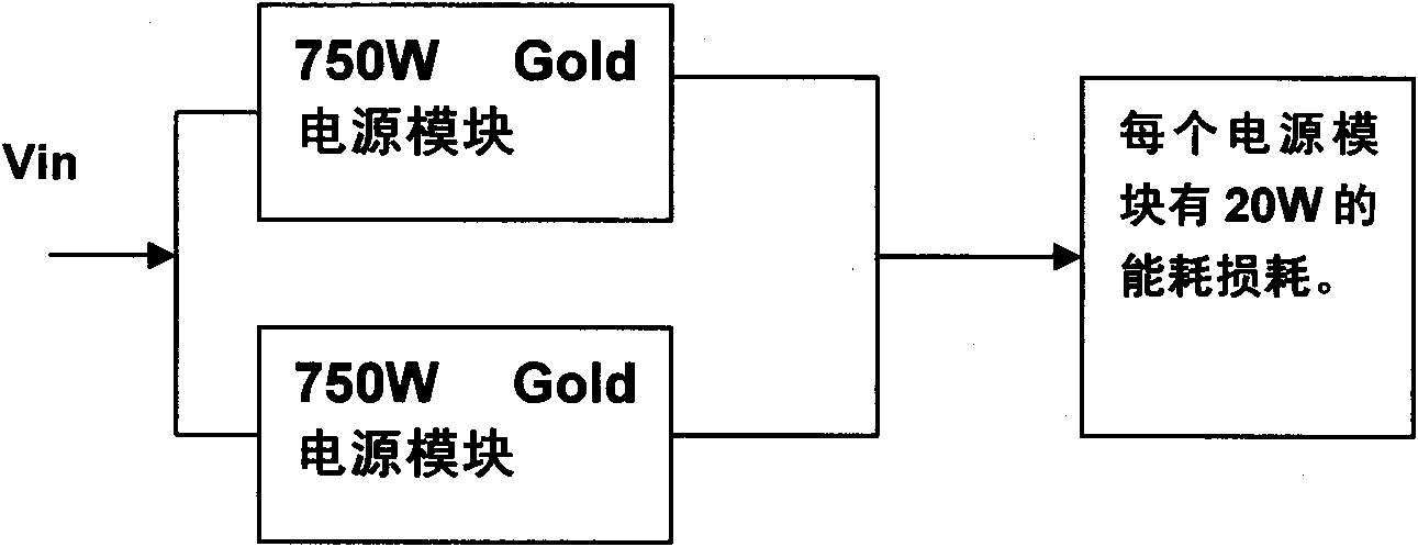
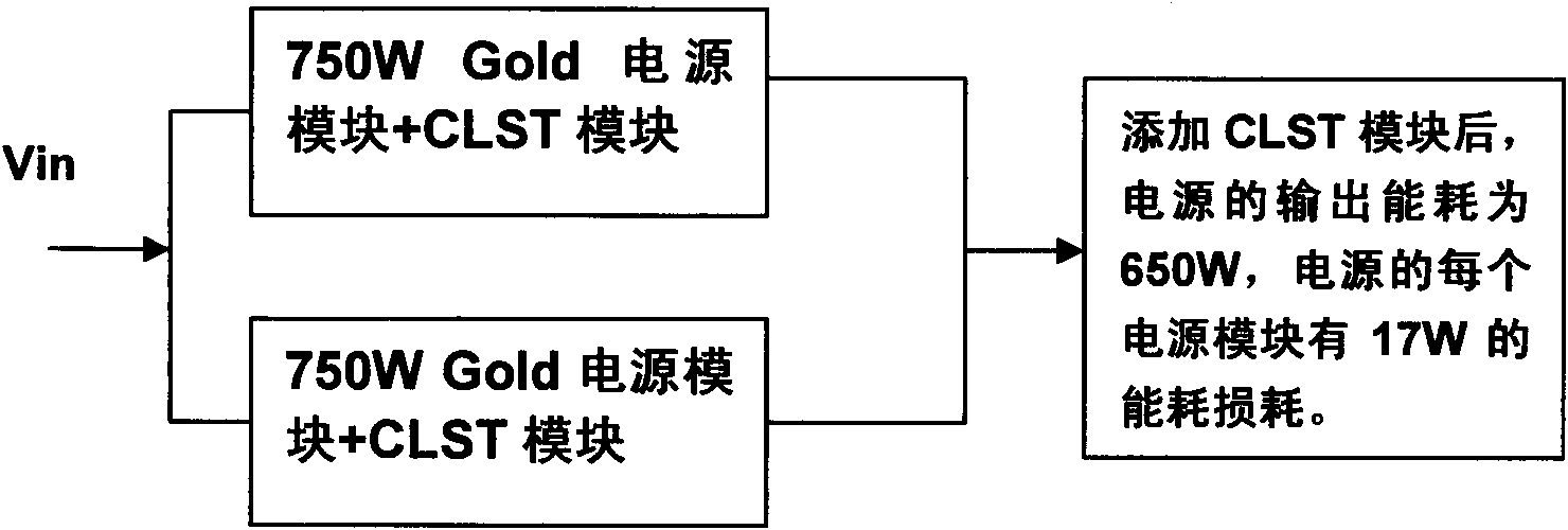
[0010] The method of the present invention is described in detail below with reference to the accompanying drawings.

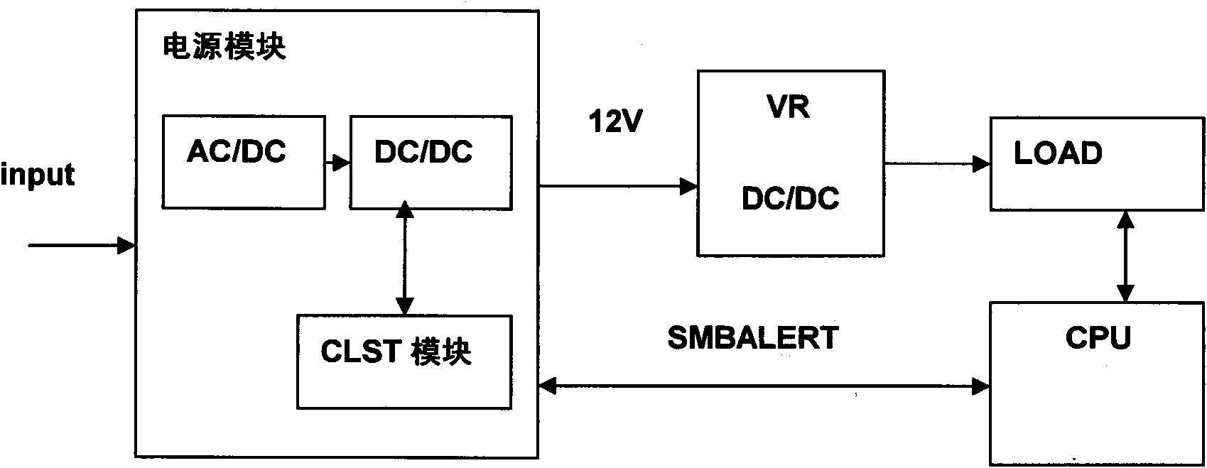
[0011] Refer to attached image 3 The method of the present invention is described in detail below.

[0012] The power supply module structure mentioned in the present invention is different from the traditional AC / DC, DC / DC power supply structure in that the module power supply of the present invention is based on the existing power supply module and integrates the CLST function module. The specific functions of the module It's like this: Estimate the power consumption data of the system according to the given machine configuration (such as: CPU, memory, hard disk, graphics card, etc. not necessarily the model and number); then, based on the fact that the system will not often continue to work under full load conditions- This actual situation is used to set a threshold value for the power consumption of the system (the threshold value will be lower than the ...


PUM


Abstract

The invention provides a method for reducing system energy consumption. A CLST functional module is arranged in AC/DC and DC/DC structures of a power module so as to form a whole power module, and the system power supply demand is met through conversion of an external voltage regulation module, wherein the CLST functional module is connected with a DC/DC structural circuit inside the power module and externally communicates with a CPU in the system through an SMBUS bus so as to monitor the power consumption of the CPU. When the system works under the full-load condition, the CLST module transmits the loaded feedback alarm signal information to a Nod Manager module in the system, the Nod Manager module notifies BIOS in the system to adjust working parameters of the CPU and a memory core component so as to automatically reduce the frequency or close actions of certain circuits, so that the whole system works under the lower load condition. Therefore, the integral energy consumption of the system is reduced, and the power cost of server equipment is saved simultaneously.

Description


Claims


Application Information

Patent Timeline
Owner LANGCHAO ELECTRONIC INFORMATION IND CO LTD
Learn More