Diagnostic method for detecting control valve component failure

A technology of control valves and pneumatic control valves, which is applied in the testing of mechanical components, testing of machine/structural components, valve devices, etc., and can solve problems such as high cost

Active Publication Date: 2011-01-26
FISHER CONTROLS INT LLC
View PDF3 Cites 29 Cited by
  • Summary
  • Abstract
  • Description
  • Claims
  • Application Information

AI Technical Summary

Problems solved by technology

However, this option is costly as the process control loop in which the control valve is applied needs to be shut down and / or the control valve removed and disassembled for inspection

Method used


Image

  • Diagnostic method for detecting control valve component failure
  • Diagnostic method for detecting control valve component failure
  • Diagnostic method for detecting control valve component failure

Examples


Embodiment Construction

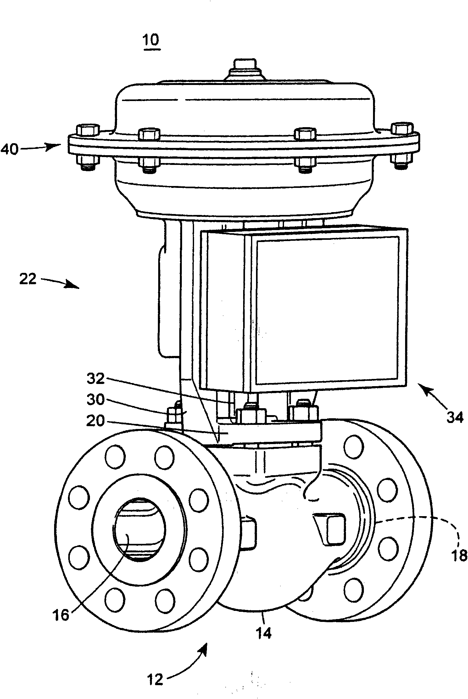
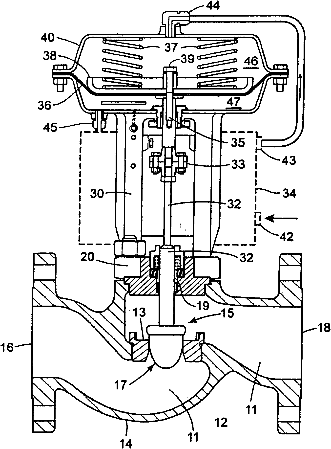
[0023] figure 1 Shown is a control valve assembly 10 that can be used in a process control system, eg, a process plant. Control valve assembly 10 includes valve 12 , actuator 22 and control valve instrumentation or positioner 34 . Valve 12 includes valve body 14 , inlet 16 , outlet 18 , and actuator 22 includes valve cover 20 and pneumatic diaphragm casing 40 . A valve stem 32 may be disposed through the bonnet 20 , which may be used to operate the valve 12 . The yoke 30 can be connected to the valve cover 20 or be provided together with the valve cover 20 . Although the yoke 30 can be attached to the valve cover 20, as figure 1 As shown, but the yoke 30 can be mounted to another part of the valve body 14 in other embodiments. A pneumatic diaphragm case 40 can be coupled to the valve body 14 using the yoke 30 . The valve stem 32 can form part of the valve stem assembly 15, as will be described further below, and can be adapted to transmit force from the pneumatic diaphrag...


PUM


Abstract

The claimed method and system identifies faults and / or deterioration of components in a process control valve (10). The system may use different sensor combinations to provide the necessary data to compute irregular component integrity. Alerts may be generated to indicate potential component integrity problems. In particular, the system may detect potential deterioration and / or faults in actuator springs (37), pneumatic tubing and piping, and bellows seals (36). The claimed system may be communicatively coupled to a process control network to provide a more elaborate alarm system. Moreover, additional statistical methods may be used to refine the detection accuracy of the system.

Description

field of invention [0001] This patent relates generally to implementing diagnostics and maintenance in process plants and, more particularly, to providing diagnostic capabilities in process plants in a manner that reduces or prevents control valve failures in process plants. Background technique [0002] Control valve failures in industrial processes have an almost constant impact on plant operations. In general, a control valve failure can affect the control valve's response to the control signal. In particular, control valves may become less responsive or slow to respond to control signals, which may result in reduced control performance causing process variability which is costly to the plant operator or worse, may lead to dangerous Condition. Accordingly, early detection of control valve degradation or damage may allow maintenance of control valves to be scheduled in a manner that prevents disruption to the operation of the process plant. [0003] Degraded control val...

Claims


Application Information

Patent Timeline
Patent Type & Authority Applications(China)
IPC IPC(8): F16K37/00
CPCF16K37/0083F16K37/0091F16K37/0075G01M13/00G01M3/00
Inventor G·D·威尔克
Owner FISHER CONTROLS INT LLC
Why Eureka
Try Eureka