
Interface module for use with a Modbus device network and a Fieldbus device network

a technology of interface module and fieldbus device, which is applied in the direction of total factory control, programme control, electric programme control, etc., to facilitate the exchange of process control information

Inactive Publication Date: 2007-07-17
ROSEMOUNT INC
View PDF12 Cites 30 Cited by
  • Summary
  • Abstract
  • Description
  • Claims
  • Application Information

AI Technical Summary

Problems solved by technology

However, despite the partial conversion, the Modbus portion of the process control network may still require information and data from the Fieldbus portion of the process control network.

Method used


Image

  • Interface module for use with a Modbus device network and a Fieldbus device network
  • Interface module for use with a Modbus device network and a Fieldbus device network
  • Interface module for use with a Modbus device network and a Fieldbus device network

Examples


Embodiment Construction

[0025]Although the following text sets forth a detailed description of numerous different embodiments of the invention, it should be understood that the legal scope of the invention is defined by the words of the claims set forth at the end of a patent. The detailed description is to be construed as exemplary only and does not describe every possible embodiment of the invention since describing every possible embodiment would be impractical, if not impossible. Numerous alternative embodiments could be implemented, using either current technology or technology developed after the filing date of this provisional patent application, which would still fall within the scope of the claims defining the invention.

[0026]It should also be understood that, unless a term is expressly defined in this provisional patent application using the sentence “As used herein, the term ‘______’ is hereby defined to mean . . . ” or a similar sentence, there is no intent to limit the meaning of that term, ei...


PUM


Abstract

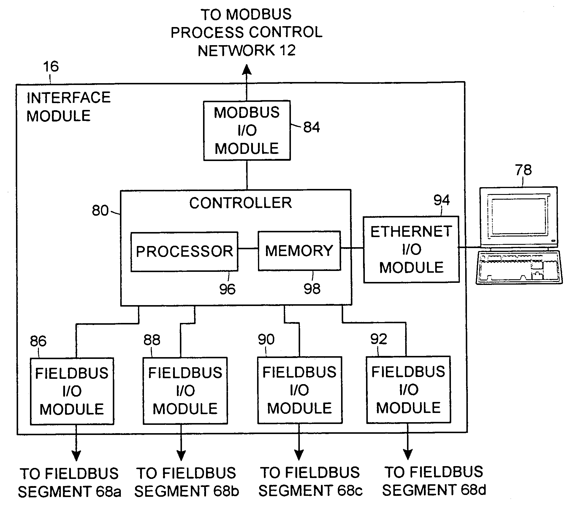
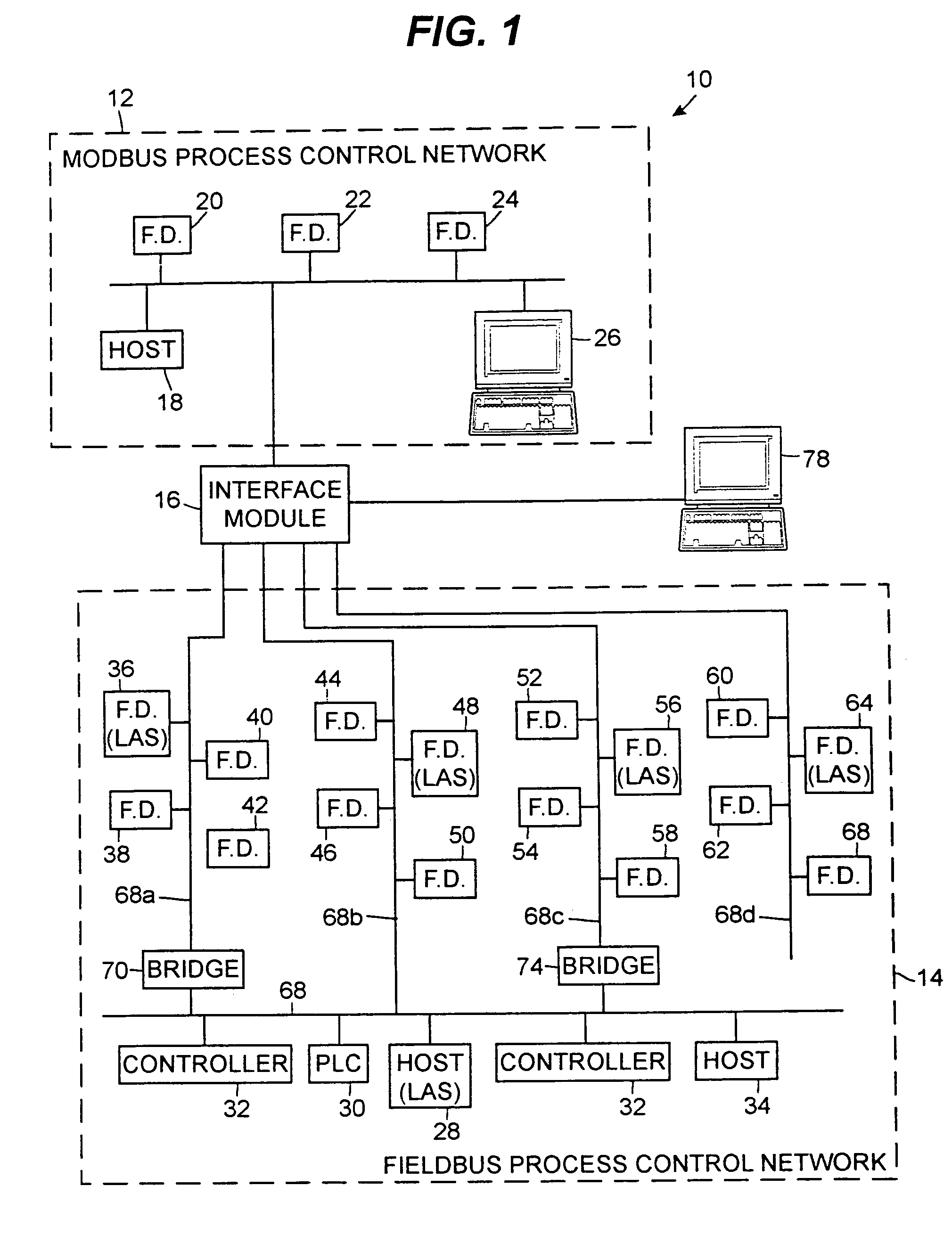
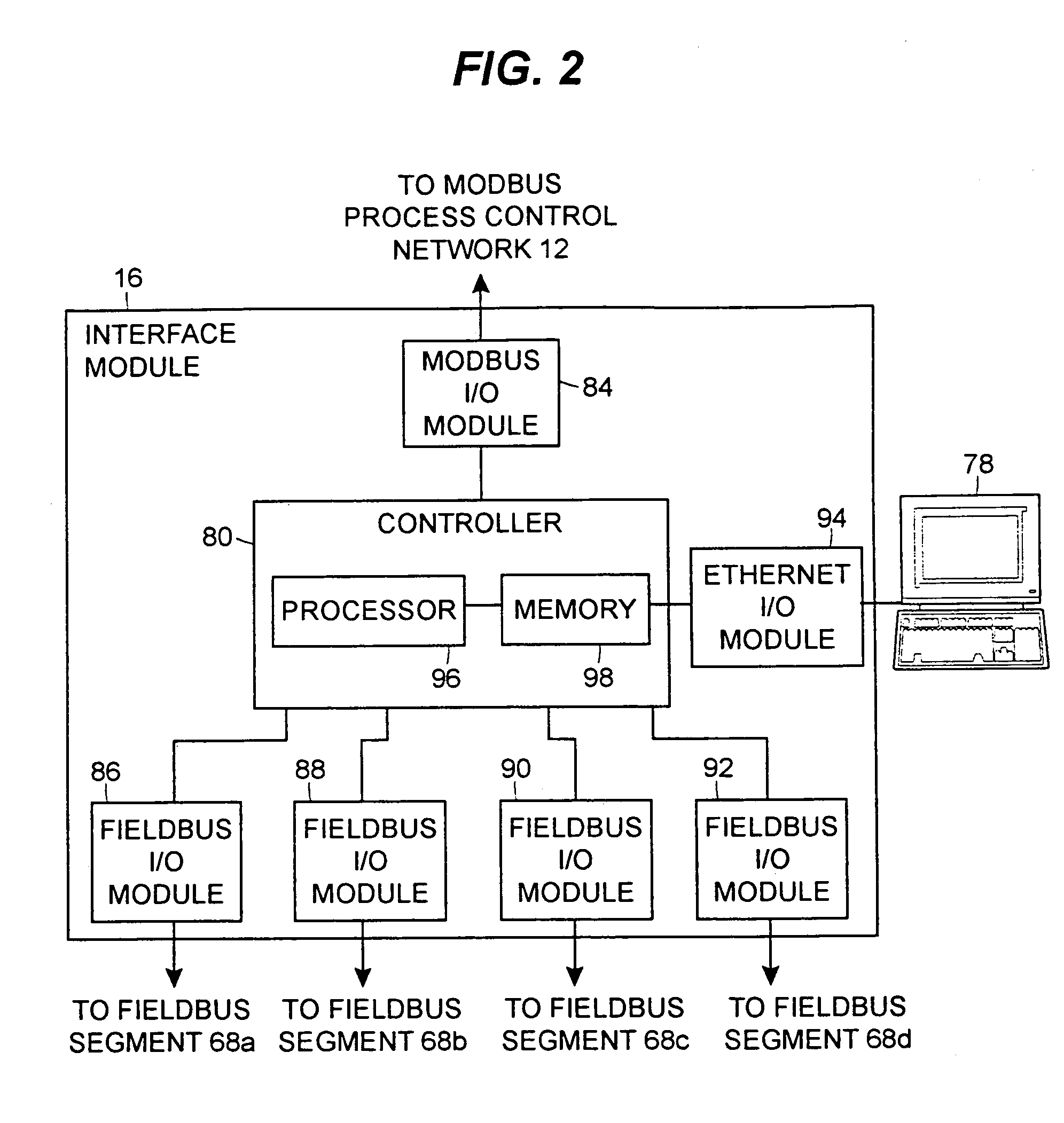
An interface module is operatively coupled to a Fieldbus process control network and a Modbus process control network to facilitate the exchange of process control information between the networks. The interface module stores a register map database in which the process control parameters of the function blocks in the field devices of the Fieldbus process control network are mapped to register numbers of the Modbus process control network. Once the Fieldbus process control parameters are mapped to the Modbus registers, the interface module is adapted to transmit request messages on the Fieldbus process control network to the Fieldbus field devices for the current values of the process control parameters, receive response messages from the Fieldbus field devices, and store the current values of the process control parameters in the register map database.

Description

FIELD OF THE INVENTION[0001]The present invention relates generally to process control systems and, more particularly, to an interface module for exchanging data between a Fieldbus device network and a Modbus device network.DESCRIPTION OF THE RELATED ART[0002]Process control systems, like those used in chemical, petroleum or other processes, typically include at least one centralized process controller communicatively coupled to at least one host or operator workstation and to one or more field devices via analog and / or digital buses or other communication lines or channels. The field devices, which may be, for example, valves, valve positioners, switches, transmitters (e.g., temperature, pressure and flow rate sensors), etc. perform functions within the process such as opening or closing valves and measuring process parameters. The process controller receives signals indicative of process measurements made by the field devices and / or other information pertaining to the field device...

Claims


Application Information

Patent Timeline
Patent Type & Authority Patents(United States)
IPC IPC(8): G06F13/36G06F13/10G06F13/20G06F13/40G05BG05B19/18G05B19/418G06F13/14H04L69/14
CPCG05B19/4186G05B2219/31122G05B2219/31326G05B2219/31335Y02P90/02
Inventor ROTVOLD, ERIC D.LATTIMER, DONALD R.GREEN, MICHAEL J.KARSCHNIA, ROBERT J.PELUSO, MARCOS A. V.
Owner ROSEMOUNT INC
Learn More