
Tool for configuring and managing a process control network including the use of spatial information

a technology of process control and spatial information, applied in the field of process control networks, can solve the problems of limited equipment that can be used or interconnected, difficult and expensive expansion of the process control system, and difficulty in extending, upgrading, reprograming and/or service, etc., and achieve the effect of efficient design and us

Inactive Publication Date: 2005-01-13
FISHER-ROSEMOUNT SYST INC
View PDF18 Cites 31 Cited by
  • Summary
  • Abstract
  • Description
  • Claims
  • Application Information

AI Technical Summary

Benefits of technology

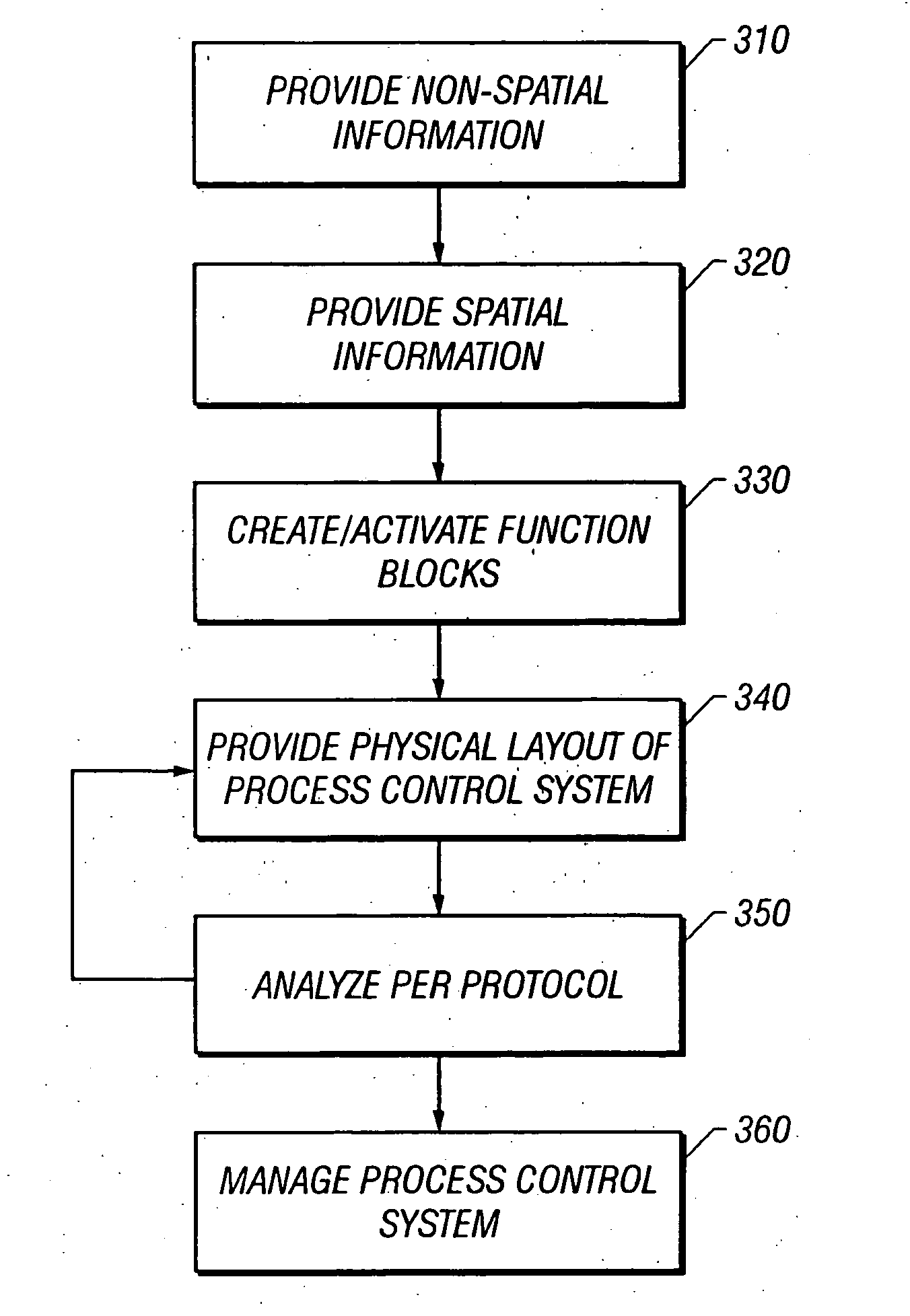
[0016] The present invention is directed to using spatial information of a facility for configuring and managing a process control system which is included within the facility. The process control system may conform to a standard protocol. Such a system advantageously allows the efficient design and use of a process control system while ensuring that the physical characteristics of the system conform to the standard. In addition, such a system also advantageously provides for more efficient diagnostics, on-line debugging, alarm managing and device maintenance.

Problems solved by technology

Usually, however, the control scheme implemented is proprietary to the field device manufacturer, thus making the process control system difficult and expensive to expand, upgrade, reprogram and / or service because the field device provider must become involved in an integral way to perform any of these activities.
Furthermore, the equipment that can be used or interconnected may be limited due to the proprietary nature of the field device and the situation where the provider may not support certain devices or functions of devices manufactured by other vendors.
These high-level languages, although effective for process control programming, are not usually used or understood by process engineers, maintenance engineers, control engineers, operators and supervisors.
When using these protocols, a challenge associated with designing the process control system or network relates to the actual physical layout and interconnection of the various process control devices.
Once the process control system or network is configured and in use, the managing of the system can be cumbersome due to the complexity of most refining and manufacturing facilities.
The monitoring software programs also signal an alarm when a problem occurs.
One challenge associated with the graphical views provided is that only logical connections are shown.
When managing the process control system, the physical location of devices and controllers must be manually determined, often increasing the amount of time required to correct a problem or mange the process control system.

Method used


Image

  • Tool for configuring and managing a process control network including the use of spatial information
  • Tool for configuring and managing a process control network including the use of spatial information
  • Tool for configuring and managing a process control network including the use of spatial information

Examples


Embodiment Construction

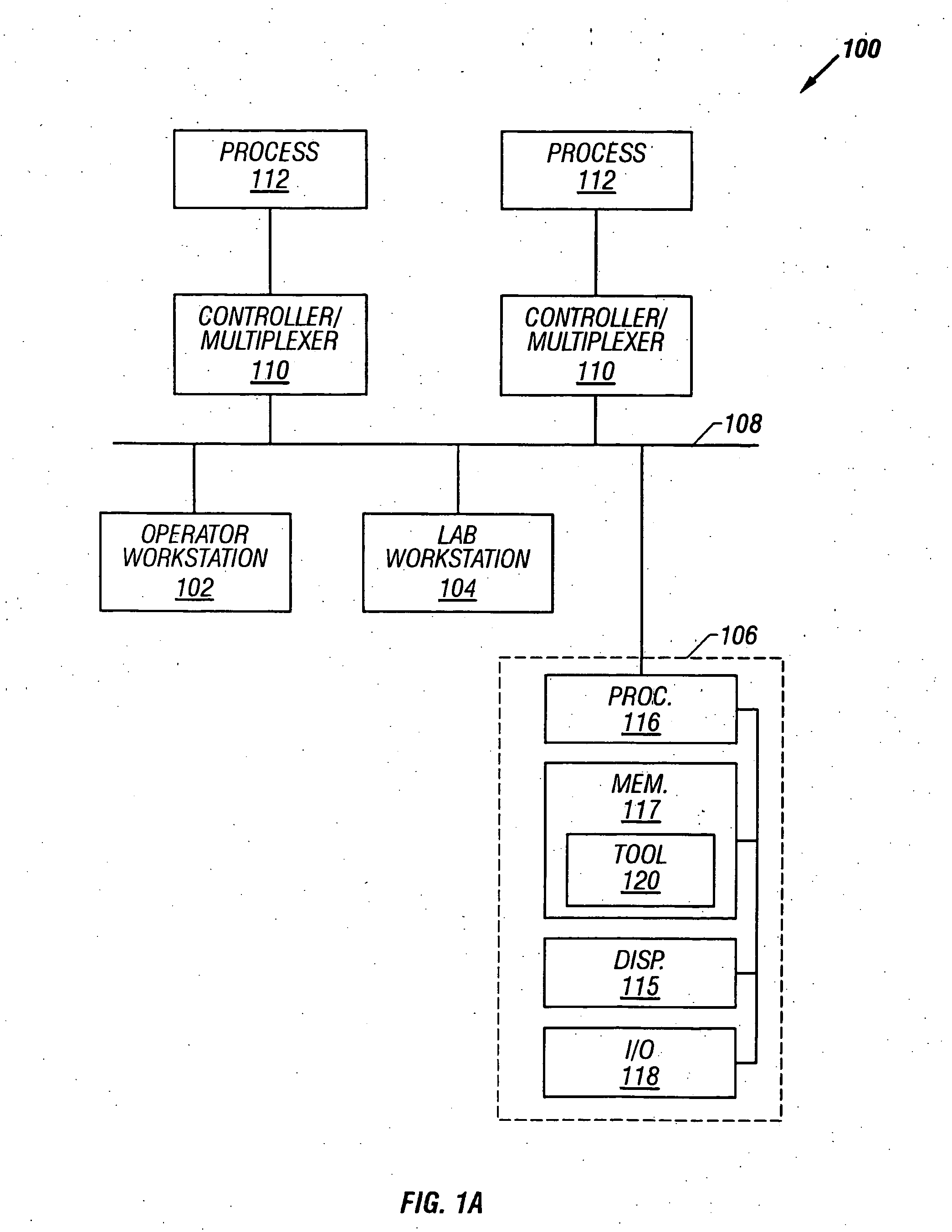
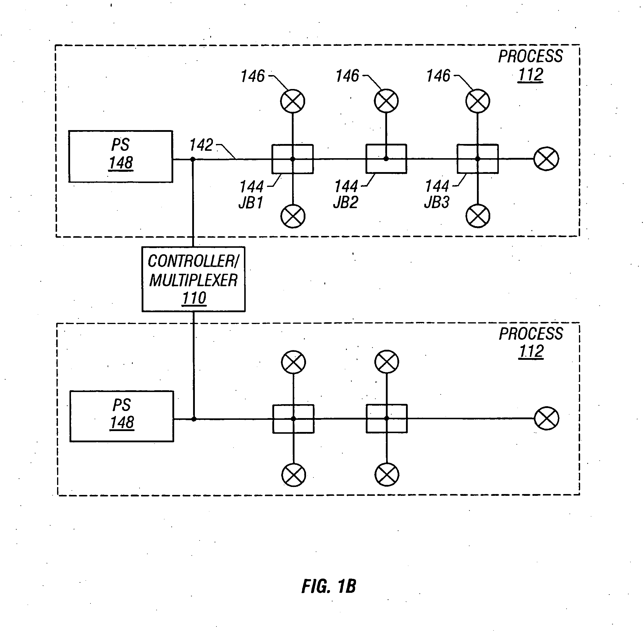
[0029] A process control environment 100 is shown in FIG. 1a and illustrates a control environment for implementing a digital control system, process controller or the like. The process control environment 100 includes an operator workstation 102, a lab workstation 104, and an engineering workstation 106 electrically interconnected by a local area network (“LAN”) 108, or other known communication link, for transferring and receiving data and control signals among the various workstations and a plurality of controller / multiplexers 110. Workstations 102, 104, and 106 are, for example, computers which conform to the IBM compatible architecture. The workstations 102, 104, and 106 are shown connected by the LAN 108 to a plurality of the controller / multiplexers 110 that electrically interface between the workstations and a plurality of processes 112. In multiple various embodiments, the LAN 108 includes a single workstation connected directly to a controller / multiplexer 110 or alternative...


PUM


Abstract

The present invention is directed to a tool which includes spatial information for configuring and managing a process control system which conforms to a standard protocol. Such a tool advantageously allows the efficient design and use of a process control system while ensuring that the physical characteristics of the system conform to the standard. In addition, the tool provides for more efficient diagnostics, on-line debugging, alarm monitoring and device maintenance.

Description

CROSS-REFERENCE TO RELATED APPLICATION [0001] This application is a continuing application to the U.S. patent application Ser. No. 09 / 488,335, filed on Jan. 20, 2000 and entitled “Tool For Configuring and Managing a Process Control Network Including the Use of Spatial Information.” Accordingly, this application relates to and incorporates herein by reference as fully set forth herein the U.S. patent application Ser. No. 09 / 488,335, filed on Jan. 20, 2000 and entitled “Tool For Configuring and Managing a Process Control Network Including the Use of Spatial Information.”FIELD OF THE DISCLOSURE [0002] The present invention relates generally to process control networks and more particularly to configuring and managing process control networks. DESCRIPTION OF THE RELATED ART [0003] Large processes such as chemical, petroleum and other manufacturing and refining processes include numerous field devices disposed at various locations within a facility to measure and control process paramete...

Claims


Application Information

Patent Timeline
IPC IPC(8): G06F17/50G05B19/418
CPCG05B19/41885G05B2219/32085G05B2219/32356G05B2219/23182Y10S715/967Y10S715/965G05B2219/32365Y02P90/02
Inventor DOVE, ANDREW PHILIPGARDNER, DAVID RICHARD
Owner FISHER-ROSEMOUNT SYST INC
Learn More