Eureka AIR delivers breakthrough ideas for toughest innovation challenges, trusted by R&D personnel around the world.

Photo acoustic sample detector with background compensation

An acoustic detector and detector technology, applied in the field of photoacoustic detectors

Inactive Publication Date: 2011-01-26
KONINK PHILIPS ELECTRONICS NV
View PDF0 Cites 5 Cited by
  • Summary
  • Abstract
  • Description
  • Claims
  • Application Information

AI Technical Summary

Problems solved by technology

The disadvantage of AM photoacoustic detectors is that the modulated laser produces a background signal at the same frequency as the sample signal of interest

Method used


Image

  • Photo acoustic sample detector with background compensation
  • Photo acoustic sample detector with background compensation
  • Photo acoustic sample detector with background compensation

Examples


Embodiment Construction

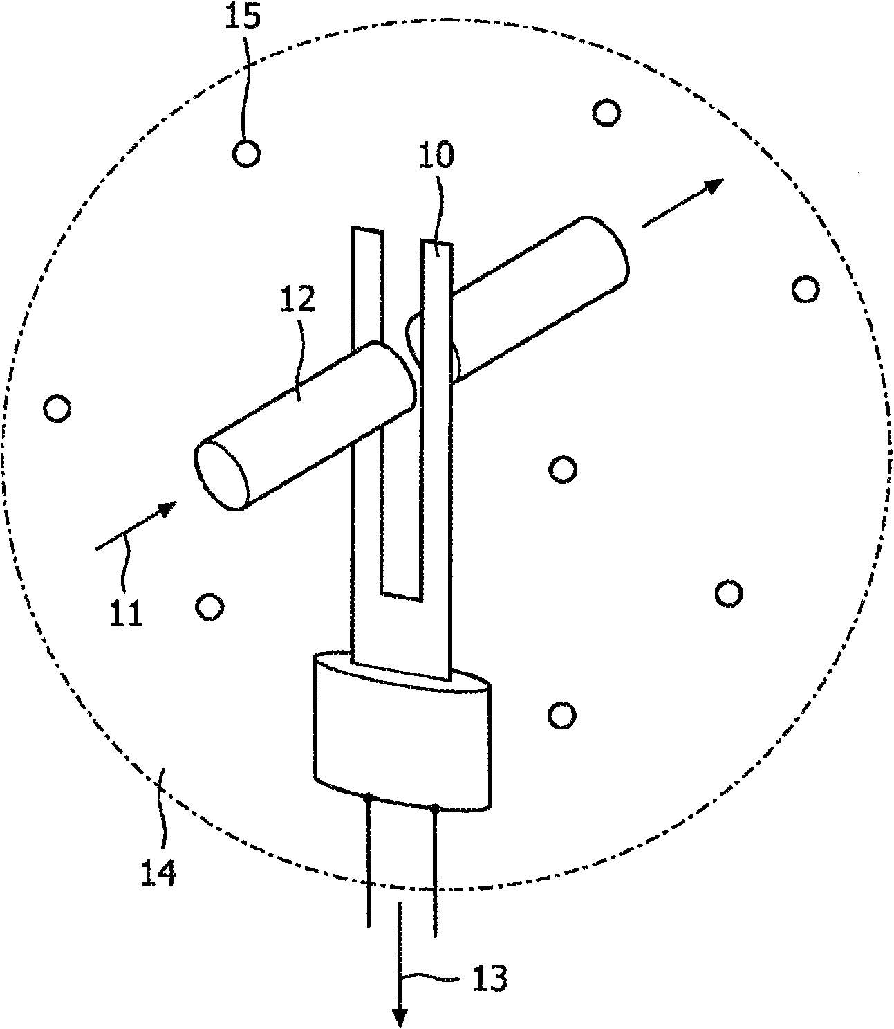
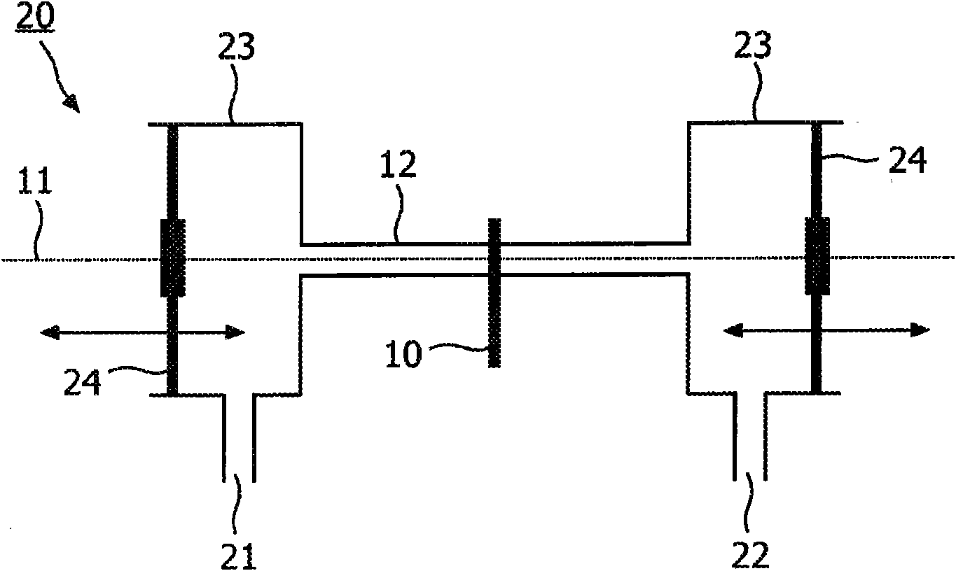
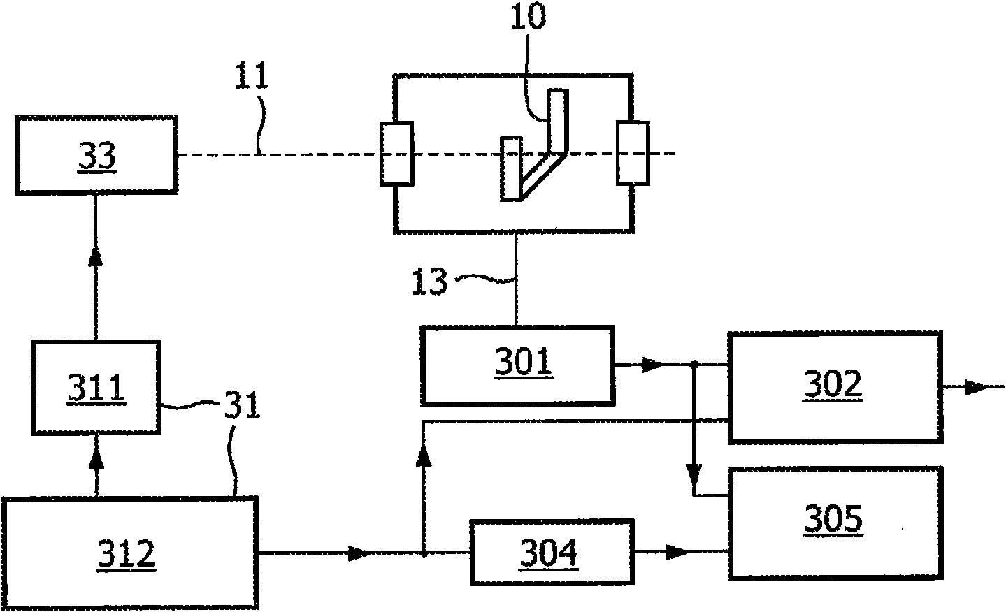
[0021] figure 1 A perspective view of a portion of a photoacoustic detector is shown. The amplitude modulated laser beam 11 passes through the gas mixture 14 . The gas mixture 14 includes a low concentration of sample molecules 15 . The laser beam 11 excites a part of the sample molecules. The return of the sample molecules from the excited state to the ground state results in a local temperature increase. The varying intensity of the laser light 11 causes pressure waves in the gas mixture 14 . Pressure waves can be detected as acoustic waves by means of a resonant pickup element, for example in the form of a piezoelectric tuning fork 10 . The tuning fork 10 may be a quartz tuning fork. The acoustic resonator 12 amplifies sound waves. The tuning fork 10 converts the sound signal into a detector signal 13, which is directed to the processing unit, where the reference image 3 with 4 Describe the processing unit in detail.

[0022] The tuning fork 10 has the advantage o...


PUM


Abstract

A photo acoustic detector for detecting a concentration of a sample in a sample mixture, the photo acoustic detector has a light source for producing a light beam for exciting molecules of the sample, a light modulator for modulating an intensity of the light beam for generating pressure variations in the sample mixture, an amplitude of the pressure variations being a measure of the concentration of the sample, and an acoustic cell with an acoustic resonator for amplifying the pressure variations. Furthermore, the photo acoustic detector has a resonant pickup element for converting the pressure variations inside the acoustic resonator into a detector signal, and a processing section for processing the detector signal to generate 1) a sample signal caused by the pressure variations, and 2) a background signal caused by direct excitation of the pickup element by the light beam. The acoustic cell and the pickup element are arranged in such a way that a phase difference between the background signal and the sample signal is close to 90 degrees.

Description

technical field [0001] The invention relates to a photoacoustic detector for detecting the concentration of a sample in a sample mixture, the photoacoustic detector comprising a light source, a light modulator, an acoustic cavity with an acoustic resonator, a resonant pickup element and a processing part. A light source generates a beam of light that excites sample molecules. The light modulator modulates the intensity of the beam to create a pressure change in the sample mixture, the magnitude of which is a measure of the sample concentration. Acoustic resonators amplify pressure changes. The pickup element converts the pressure change into a detector signal. The processing section processes the detector signals to generate sample signals resulting from pressure changes. The invention also relates to a method of manufacturing such a photoacoustic detector. Background technique [0002] This photoacoustic detector is used in industry for trace gas monitoring and in the f...

Claims


Application Information

Patent Timeline
Patent Type & Authority Applications(China)
IPC IPC(8): G01N21/17
CPCG01N21/1702Y10T29/49826
Inventor J·卡尔克曼H·W·范克斯特伦
Owner KONINK PHILIPS ELECTRONICS NV
Why Eureka
Eureka Blog
Learn More