Automobile

A technology for automobiles and car bodies, which is applied in the direction of car bodies, body stability, and vehicle components, and can solve problems such as damage and threats to vehicle driving safety

Active Publication Date: 2011-02-02
朱晓义
View PDF0 Cites 16 Cited by
  • Summary
  • Abstract
  • Description
  • Claims
  • Application Information

AI Technical Summary

Problems solved by technology

Therefore, reducing the distance difference between the chassis of the car and the road is the most feasible way to reduce the lift resistance. However, the height of the chassis of the car is directly related to the condition of the road on which the vehicle is driving. Direct contact with friction causes damage and even poses a threat to vehicle safety

Method used


Image

  • Automobile
  • Automobile
  • Automobile

Examples


Embodiment 1

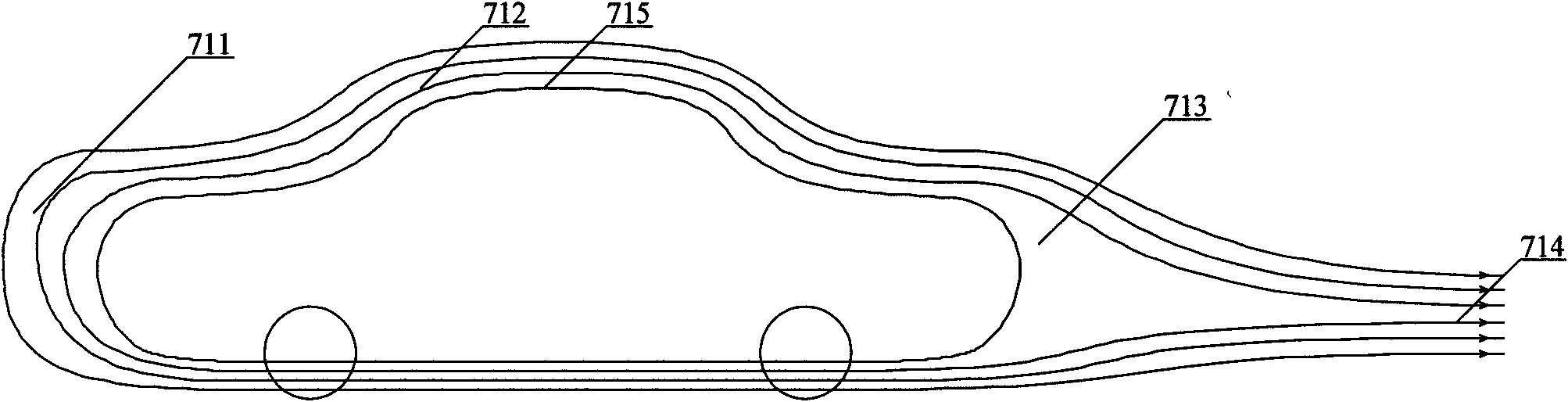
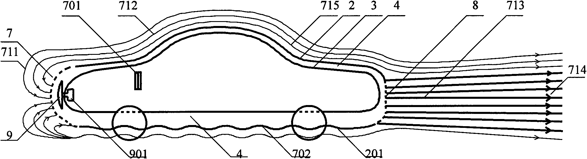
[0033] Such as figure 2 As shown, a car has a spoiler device added to the bottom of the car to increase the running speed and reduce energy consumption. A first inlet 7 is provided at the front end of the automobile. The first inlet 7 forms an annular fluid channel 4 that surrounds the vehicle body through a certain distance between the outer shell 2 and the inner shell 3, and the outlet 8 is provided at the rear end to penetrate back and forth. A rotating head 9 driven by a motor 901 is provided in the first inlet 7. At least one third side guide inlet 701 is provided around the vehicle body to communicate with the fluid channel 4, the bottom shell 2 is a spoiler 201 that is alternately concave and convex, and at least one second balanced inlet 702 is provided on the spoiler 201. The spoiler surface The distance between 201 and the ground is fixed, which does not affect the car's driving on normal roads. When the fluid passes through an unlimited distance between the spoiler ...

Embodiment 2

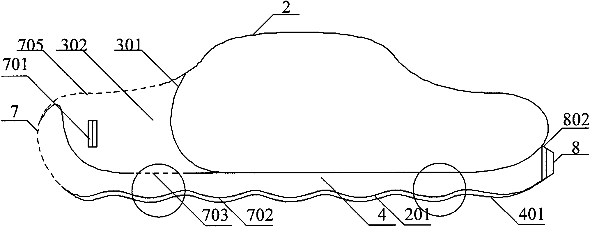
[0036] Such as image 3 As shown, it is a kind of automobile, and the structure can be most directly and simply applied to various existing car bodies. It achieves the energy-saving goal by fixing the improvement of the spoiler device under the vehicle to reduce the fluid resistance and lift resistance.

[0037] The car body includes a casing 2 and a spoiler 201 is added to the bottom of the casing 2 to reduce the distance between the ground and the road surface of the car body casing 2 to reduce the fluid flow rate in the lower part, thereby reducing lift resistance. Moreover, the surface of the spoiler 201 is further formed into a concave-convex shape, so that the path of the fluid when passing through the spoiler 201 is larger than the path of the upper part of the car shell 2, so as to form a top-down pressure difference when the vehicle is running, and eliminate the fluid Lift resistance.

[0038] If it is necessary to further reduce the resistance experienced by the vehicle ...

Embodiment 3

[0042] Such as Figure 4 , Figure 5 As shown, a car with a movable and controllable spoiler device at the bottom includes a car body 1. The car body 1 is provided with a spoiler device 2 at the bottom. The spoiler device 2 is connected to a movable rod 204 with adjustable vertical height. The inner bottom is connected, the spoiler device 2 is also arranged in a non-close contact with the car body 1, and an isolation layer 202 is also arranged in between, thereby forming an upper fluid channel 401 and a lower fluid channel 4, and the front end of the car body 1 is provided with a first An inlet 7 is provided with outlets 8 and 801 at the rear end. The first inlet 7 communicates back and forth with the lower fluid channel 4 and the outlet 8, and the first inlet 7 communicates with the upper fluid channel 401 and the outlet 801. The surface of the spoiler device 2 and the surface of the isolation layer 202 are both concave and convex spoiler surfaces 201 and 202, so that the path ...


PUM


Abstract

The invention provides an automobile, comprising a body. The automobile has the following beneficial effects: arranging a flow disturbing device which can change the distance between the bottom of the automobile and the pavement at the bottom of the automobile so as to realize the aim of reducing the lift force borne by the automobile during running; providing the flow disturbing device linked by movable rods, an air cushion with a reset mechanism and a fixed embodiment of three kinds of flow disturbing devices, realizing determining the distance between the two surfaces by controlling the bottom of the automobile to lift under the condition of not affecting running of the automobile on the common pavement, ejecting vast fluid received from a front lead-in hole and lead-in holes around from lead-out holes by communicating the lead-in hole at the front end of the automobile and the lead-in holes around with fluid channels and the rear lead-out holes to prevent fluid openings from being sealed, so that the rear negative pressure area disappears and the large negative pressure area of the fluid openings is impossible to form, and changing the rear negative pressure area to the relative positive fluid area, thus all the fluid resistance problems during automobile running can be readily solved to achieve the aim of energy saving.

Description

【Technical Field】 [0001] The invention relates to an automobile, in particular to an automobile that can effectively reduce fluid resistance and lift resistance during vehicle operation. 【Background technique】 [0002] Conventionally, the vehicle needs to hit the front fluid wall during operation. The fluid wall that hits will instantly form a fluid hole tightly wrapping the car body. When the fluid hole reaches the rear of the vehicle at the same time, it will form a negative pressure zone and the car will be trapped. The resulting large negative pressure area is tightly dragged by the fluid resistance and requires a lot of energy to overcome it. Therefore, how to prevent the fluid hole from being closed, and how to make the fluid hole itself appear unbalanced to disrupt the formation of resistance and reduce the energy consumption of the vehicle is also one of the key methods to reduce the energy consumption of the vehicle. When the car is driving fast, the smaller the distanc...

Claims


Application Information

Patent Timeline
Patent Type & Authority Applications(China)
IPC IPC(8): B62D37/02
Inventor 朱晓义
Owner 朱晓义
Why Eureka
Try Eureka