Elevator

A technology for elevators and control cables, which is applied in the field of elevators, and can solve the problems of increased cable weight, the limit of the size of the elevator's lifting stroke, and large eccentric loads.

Inactive Publication Date: 2011-02-02
MITSUBISHI ELECTRIC CORP
View PDF1 Cites 2 Cited by
  • Summary
  • Abstract
  • Description
  • Claims
  • Application Information

AI Technical Summary

Problems solved by technology

[0005] However, in such conventional elevators, if a thick and high-strength reinforcing wire is used, the dead weight of the control cable increases, and there are problems such as the following: If the control cable is not suspended near the center of the car, the unbalanced load will be very large. Big
[0007] Like this, as the problem in the existing elevator, there are the following problems: Since it is necessary to use control cables with different bending radii and reinforcing steel wires, it is necessary to use a plurality of types of cables; Due to the unbalanced load on the car, the control cable needs to be suspended near the center of the car; the cost is increased due to the use of thick and high-strength reinforcing steel wire; and the suspendable length is based on the self-weight of the control cable or the strength of the reinforcing steel wire The limit value of the elevator may reach the upper limit, so the size of the lifting stroke of the elevator will produce a limit

Method used


Image

  • Elevator
  • Elevator
  • Elevator

Examples


Embodiment approach 1

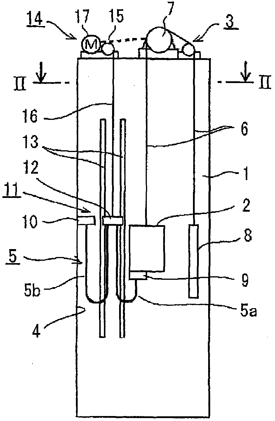
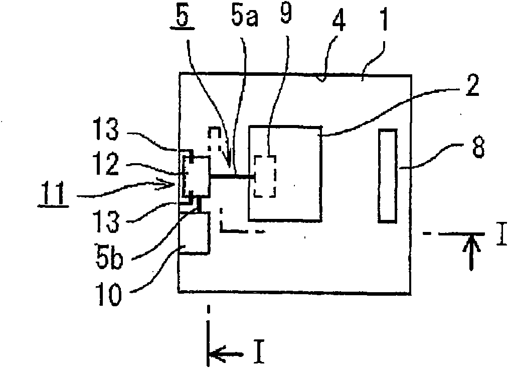
[0024] exist figure 1 Among them, the elevator of the present invention includes: a car 2, which moves along the hoistway 1; a car driving device 3, which moves the car 2; and a control cable 5, one end of which is connected to the hoistway wall 4 forming the hoistway, and the other end Connect with car 2. The car driving device 3 includes a main rope 6 connected to the car 2 and a hoist 7 around which the main rope 6 is wound, and a counterweight 8 is connected to the other end of the main rope 6 . One end of the control cable 5 is connected to the car 2 through a hanger 9 provided on the bottom wall of the car 2 . The other end of the control cable 5 is connected to a fixed hanger 10, the fixed hanger 10 is installed on the car guide rail not shown in the hoistway wall 4, and is arranged on the hoistway wall 4 for the lifting stroke of the car 2, that is, Approximate middle of the distance moved.

[0025] The elevator also has a mobile hanger device 11 which supports the ...

Embodiment approach 2

[0035] exist Figure 5 In the shown elevator, the traction sheave 15 of the driving device 14 of the mobile hanger device 11 is configured to be driven by the hoisting machine 7 of the car driving device 3 . In addition, the rope 16 suspended from the traction sheave 15 is connected to the movable hanger 12 in a 2:1 roping manner via a pulley 33 . That is, one end of the rope 16 is hung on the traction machine 7 of the car driving device 3, and the other end is hung on the traction sheave 15 and extends downward, and is hung on the pulley 33 installed on the movable hanger 12. Turn back upwards and connect with the floor of the machine room or the top wall 34 of the hoistway. other structures and Figure 1 ~ Figure 4 The structure shown is the same.

[0036] In this configuration, when car 2 starts from Figure 5 As shown, when the car 2 is located in the middle of the hoistway and starts to rise, the moving hanger 12 also rises in conjunction with it, but since the moving...

Embodiment approach 3

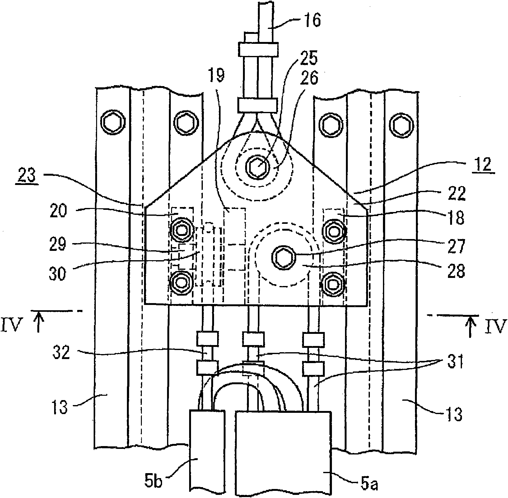
[0039] exist Figure 8 In the shown elevator, the mobile hanger device 11 has the same Figure 1 to Figure 5 In addition to the movable hanger 12 as the first movable hanger connected to the car-side cable portion 5a with the same structure as shown, there is also an intermediate movable hanger 35 as the second movable hanger. That is, the mobile hanger device 11 includes: a mobile hanger 12 connected to the car side cable portion 5a connected to one end side of the control cable 5, that is, the car 2 side; and an intermediate mobile hanger 35, which is connected to the hoistway side cable part 5b, which is connected to the other end side of the control cable 5, that is, the side of the hoistway wall 4, and the control cable 5 includes a middle cable part 5c, which will move the hanger 12 and the middle mobile hanger 35 are connected to each other.

[0040] Regarding the mobile hanger 12 as the first mobile hanger, with image 3 and Figure 4 The structure shown is the sam...


PUM


Abstract

The invention provides an elevator. A suspension length of a control cable is relative small relative to a lifting stroke. The elevator comprises a control cable, wherein one end of the control cable is connected with a lift well and another end is connected with an elevator car. In the elevator, the middle part of the control cable is supported by a movable lifting device and the movable liftingdevice lifts respective with the lifting of the elevator car in the lift well and the lifting distance of the movable lifting device is shorter than the moving distance of the elevator car. The movable lifting device comprises: a movable lifting rack connected with the control cable; a guide rail supporting the movable lifting rack to life in the lift well; and a driving device for making the movable lifting rack move along the guide rail. The lifting length of the control cable is reduced relative to the stroke of the elevator car.

Description

technical field [0001] The present invention relates to elevators, and more particularly to elevators having control cables connected to the car. Background technique [0002] Existing elevators generally consist of: one end of the control cable (lead wire) connecting the car and the hoistway equipment is connected to the hoistway, and the other end is connected to the car, so that it is suspended into a roughly U-shape. Move up and down in tandem. For control cables, various types of control cables are used depending on the number of conductors required or the bending radius. The so-called bending radius is a parameter related to the flexibility of the control cable that determines the U-shape when the control cable is suspended. [0003] Existing control cables (lead wires) include: power supply lines and signal transmission lines, which are used for power supply and signal transmission between the car and the control panel arranged in the machine room; and reinforcement...

Claims


Application Information

Patent Timeline
Patent Type & Authority Applications(China)
IPC IPC(8): B66B7/06B66B9/00B66B11/08
Inventor 石川雅洋
Owner MITSUBISHI ELECTRIC CORP
Why Eureka
Try Eureka