Time Flow Valve

A technology of fluid outlet and fluid inlet, which is applied in the field of fluid valves and can solve problems such as large moving valves

Inactive Publication Date: 2011-02-02
MICROFLOW INTERNATIONAL PTY LTD
View PDF0 Cites 0 Cited by
  • Summary
  • Abstract
  • Description
  • Claims
  • Application Information

AI Technical Summary

Problems solved by technology

In conventional valves, the force required to move the valve is very high

Method used


Image

  • Time Flow Valve
  • Time Flow Valve
  • Time Flow Valve

Examples


Embodiment Construction

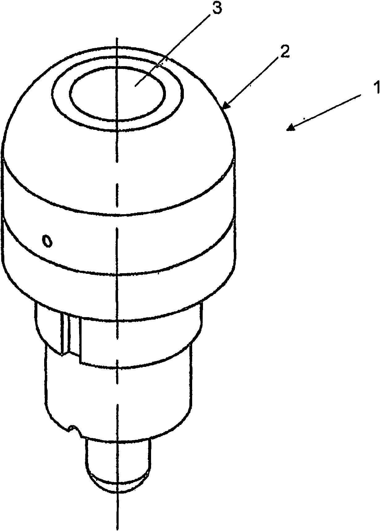
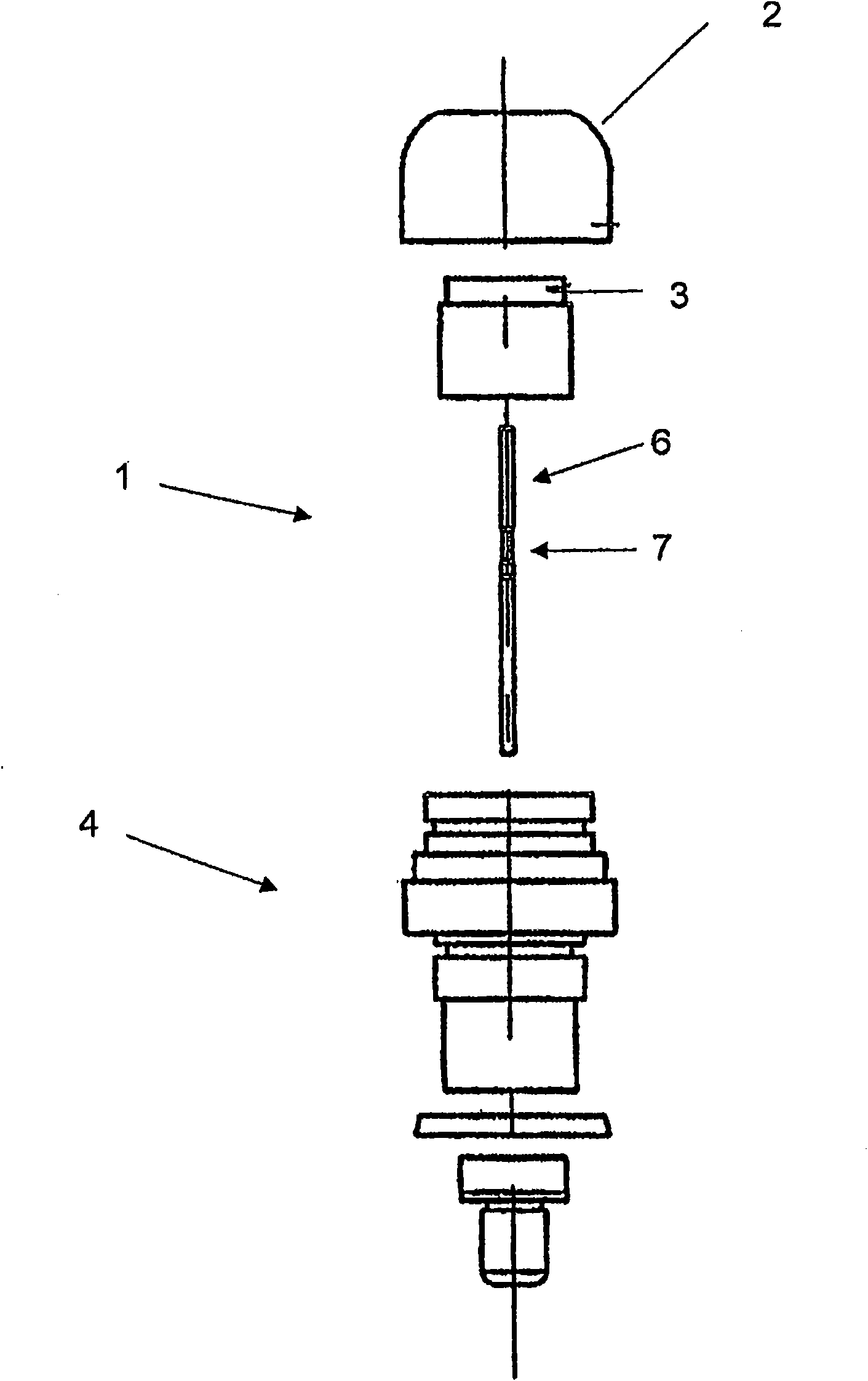
[0054] figure 1 An isometric view of a time delay fluid valve, referenced 1, according to the present invention is shown. During installation, the delay fluid valve 1 of the present invention can have various appearances, but figure 1 Appearance of the shown time-delay fluid valve 1 The shown valve 1 has a housing 2 and an activation button 3 . In operation, once installed, the user simply presses the actuation button 3 to start the actuation cycle and operate the valve. The valve is then operated for a period of time and then automatically closed. As will be described later, the start-up period can be adjusted according to various design techniques. The time-delay fluid valve of the present invention is suitable for many situations, especially public bathrooms and the like, where the valve needs to be operated for a certain period of time, such as 10 seconds, and then the valve will be automatically closed, so that no water is wasted. figure 1 The time delay fluid valve s...


PUM


Abstract

A fluid valve which opens for a predetermined time before automatically closing. The valve (101) incorporates a control means including a control chamber (103), a first / inlet passageway (102) and a second / outlet passageway (120). A flow control element (104) is provided in one of the passageways (102) or (120). A biasing means (117) normally biases the valve to a first / closed position (Figure 3). An activation means (113) is adapted to move the flow control element (104) to an activated position (Figure 4) wherein flow of fluid is then permitted for a predetermined time.

Description

technical field [0001] The present invention relates to a fluid valve, and more particularly to a fluid valve which, when activated, opens for a predetermined period of time before automatically closing. The present invention also provides a valve which, in a preferred embodiment, provides the additional function of being manually closed at any time before closing automatically. [0002] The valve of the present invention is a pressure balanced pilot operated valve incorporating an automatically movable flow control element structure. Background technique [0003] Reference in this specification to any prior publication (or information obtained therefrom) or to any known content is not, and should not be deemed to be, an endorsement or acknowledgment or any form of implication that such prior publication (or information obtained therefrom) or any known content constitutes part of the common general knowledge in the field to which this specification relates. [0004] Conven...

Claims


Application Information

Patent Timeline
Patent Type & Authority Applications(China)
IPC IPC(8): F16K13/08F16K21/04
CPCF16K21/12Y10T137/0318Y10T137/6851Y10T137/86389Y10T137/794
Inventor 伊莱亚斯·哈贾尔
Owner MICROFLOW INTERNATIONAL PTY LTD
Why Eureka
Try Eureka